estimating motor current

There has been some recent testing that has been looking at both the speed-torque curves for the 269 and 393 motors and also the control value to actual motor speeds when the motor is free running. It occurred to me that there is enough information contained in this data to estimate the current a motor is using. Having estimated the motor average current, decisions could be made as to when the motor and/or cortex PTCs may trip and evasive actions taken.

The code I’m going to post is a work in progress, it gives a pretty good value but is not 100% accurate and needs more tweaking. I though it would still be worth posting as perhaps someone else could also work on this and I’m sure improve on it.

The basic idea is as follows.

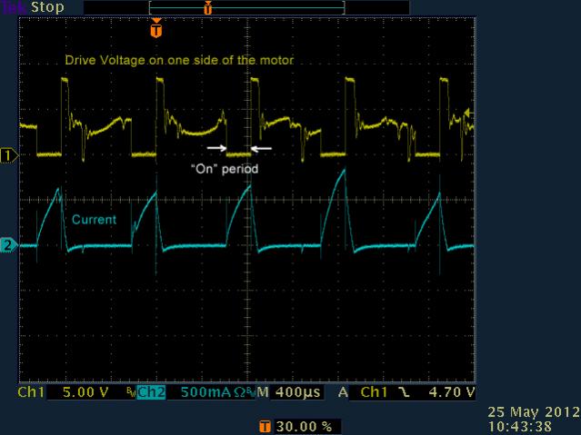
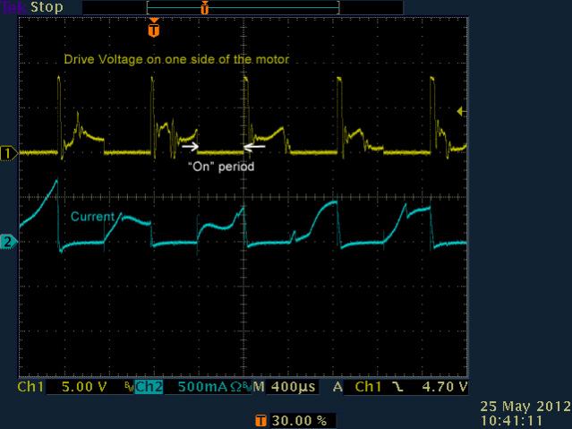
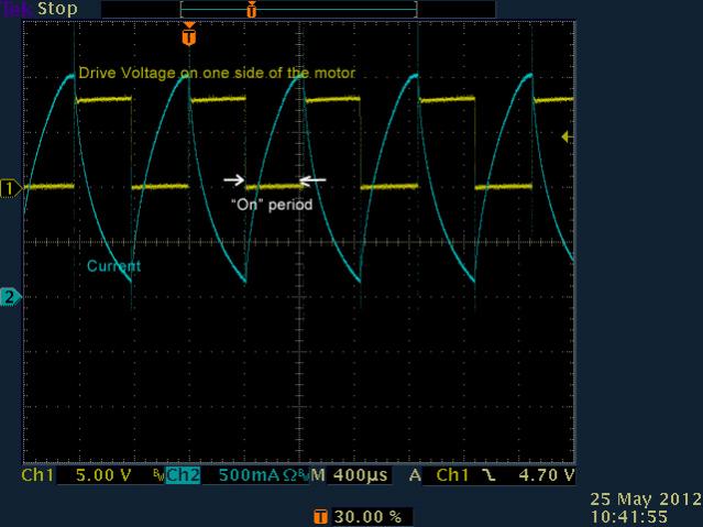
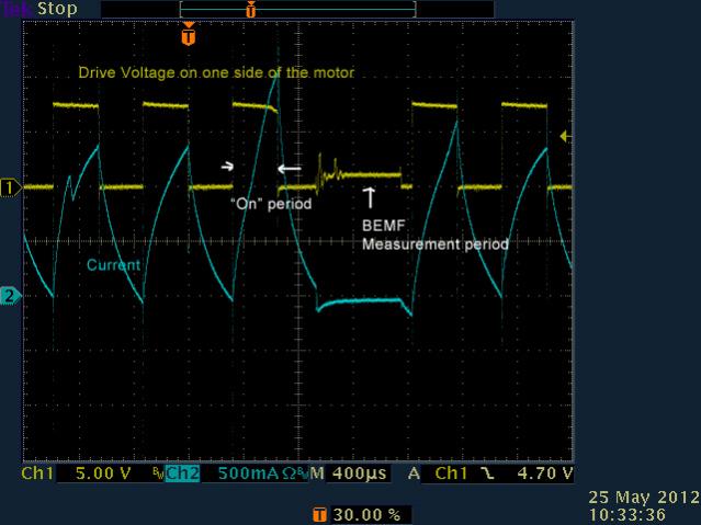
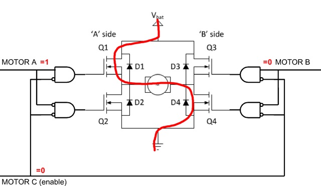
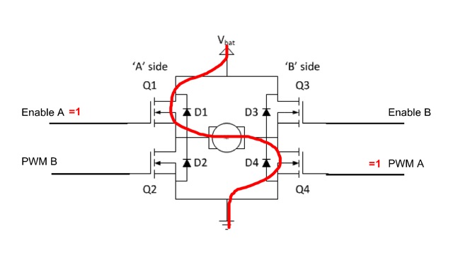
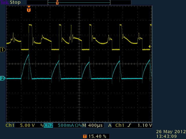
We know the control value that is sent to the motor, it creates a pwm drive signal that is proportional and therefore allows calculation of the average voltage sent to the motor.

We can measure the speed of the motor using an IME (or other encoder directly coupled to it). We know what the free running speed of the motor should be based on the control value sent so can therefore calculate the percentage of the free run speed we are at.

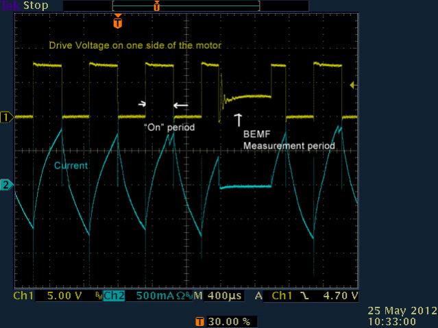
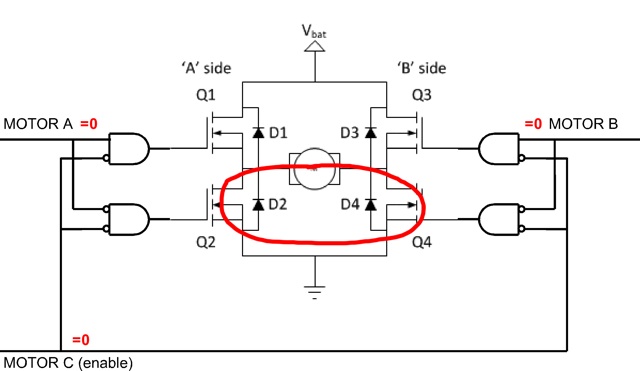
The motor will generate a back emf based on it’s speed, the back emf is an opposing voltage to the drive voltage and tends to cancel it out, this why as the motor is slowed down the motor current increases and along with that the torque.

The code estimates current by first estimating the back emf based on the measured motor speed and subtracting that from the drive voltage to create a net voltage. This is divided by a theoretical motor resistance to estimate current.

This code has been tested with a 269 motor and is accurate to within perhaps 20%, not great but if the idea is to know that you are over the 1.5A limit then it’s probably good enough. As I said above, it’s a work in progress and I’m sure could be improved.

This code below is for a 269 motor on a 3-wire port (port9) driven by a motor controller 29. I have only tested one motor and have not had time to test on a 2 wire port. This is a ROBOTC example but the same principle could be applied in EasyC.

#pragma config(UART_Usage, UART1, VEX_2x16_LCD, baudRate19200, IOPins, None, None)
#pragma config(I2C_Usage, I2C1, i2cSensors)
#pragma config(Sensor, I2C_1, motorA_enc, sensorQuadEncoderOnI2CPort,    , AutoAssign)
#pragma config(Motor,  port9, motorA, tmotorVex269, openLoop, encoder, encoderPort, I2C_1, 1000)
//*!!Code automatically generated by 'ROBOTC' configuration wizard               !!*//

/*-----------------------------------------------------------------------------*/
/*                                                                             */
/*  LUT for control value to expected rpm for a 269 motor in a 2 wire port     */
/*                                                                             */
/*-----------------------------------------------------------------------------*/

const unsigned char SpeedLut[128] =
{
  0,  0,  0,  0,  0,  0,  0,  0,  0,  1,  5,  9, 13, 17, 20, 24,
 27, 30, 33, 36, 39, 42, 44, 47, 49, 52, 54, 56, 59, 61, 63, 64,
 66, 68, 70, 71, 73, 74, 76, 77, 79, 80, 81, 82, 83, 84, 85, 86,
 87, 88, 89, 90, 91, 92, 92, 93, 94, 94, 95, 95, 96, 96, 97, 97,
 98, 98, 99, 99, 99,100,100,100,101,101,101,102,102,102,103,103,
103,103,104,104,104,104,105,105,105,105,105,106,106,106,106,107,
107,107,107,108,108,108,108,108,109,109,109,109,110,110,110,110,
111,111,111,111,111,112,112,112,112,112,113,113,113,113,113,114
};

/*-----------------------------------------------------------------------------*/

// being lazy and using globals
float motor_rpm;
float motor_current;
int   requested_speed;

/*-----------------------------------------------------------------------------*/
/*                                                                             */
/*    Try and estimate the motor current based on the current control value,   */
/*    the expected motor speed with no load and the actual motor speed.        */
/*                                                                             */
/*    This is a work in progress and gives a value for current that is in the  */
/*    ballpark but is not exactly correct.  The idea here is to get an idea of */
/*    when a PTC may trip.                                                     */
/*                                                                             */
/*-----------------------------------------------------------------------------*/

float
CalcCurrent269( tMotor m, int speed, int rpm )
{
    int   control_speed;
    int   expected_rpm;
    
    float battery_voltage;
    float pwm_time;
    float drive_voltage;
    float bemf_voltage;
    float net_voltage;
    float motor_current;
        
    // Get battery voltage in volts
    battery_voltage = nAvgBatteryLevel/1000.0;
    
    // calculate the time that the motor is being driven by the pwm signal
    // This varies from 0 to 1.0, for example, 0.5 would mean 50% duty cycle
    // and would occur when the speed was 64.
    pwm_time = (float)abs(speed) / 127.0;

    // calculate the average voltage driving the motor
    drive_voltage = pwm_time * battery_voltage;
    
    // rescale control value
    // ports 2 through 9 behave a little differently
    if( m > port1 && m < port10 )
      control_speed = abs(speed * 128 / 100);
    else
      control_speed = abs(speed);
    
    // limit to 127
    if( control_speed > 127)
        control_speed = 127;
    
    // get the expected motor speed based on the control_value
    expected_rpm = SpeedLut control_speed ];

    // calculate the back emf (possible)
    bemf_voltage = (float)abs(rpm) / (float)expected_rpm * drive_voltage;
    // bemf voltage cannot be less than 0
    if( bemf_voltage < 0 )
        bemf_voltage = 0;
      
    // calculate a possible net voltage accross the motor      
    net_voltage = drive_voltage - bemf_voltage;
    
    // calculate the current assuming motor resistance is 3 ohms
    // this gives about 2.5A at 7.5v using the max control value
    // with the motor stalled
    motor_current = (net_voltage / 3);
    
    return( motor_current );
}

/*-----------------------------------------------------------------------------*/
/*                                                                             */
/*  A task to monitor the motor IME, calculate the current motor speed and     */
/*  the motor current.                                                         */
/*                                                                             */
/*-----------------------------------------------------------------------------*/

task calcSpeed()
{
    static  int delayTimeMs = 500;
    
    long enc;
    long oldenc;
    float delta;

    while(1)
        {
        // Get encoder value
        enc = nMotorEncoder[motorA];

        // calculate encoder delta
        delta  = enc-oldenc;
        oldenc = enc;

        // calculate the rpm for a 269 motor
        motor_rpm = (1000.0/delayTimeMs) * delta * 60.0 / 240.448;

        // calculate current for a 269 motor
        motor_current = CalcCurrent269( motorA, requested_speed, motor_rpm );

        // wait
        wait1Msec(delayTimeMs);
        }
}

/*-----------------------------------------------------------------------------*/
/*                                                                             */
/*  Main task, control one motor with the joystick and display program         */
/*  variables.                                                                 */
/*                                                                             */
/*-----------------------------------------------------------------------------*/

task main()
{
    string str;
    
    // I like the LCD backlight on
    bLCDBacklight = true;

    // start the encoder/current calculation task
    StartTask( calcSpeed );
    
    // clear LCD
    clearLCDLine(0);
    clearLCDLine(1);

    // run forever
    while(1)
        {
        // get channel 1 joystick value
        requested_speed = vexRT[Ch1];

        // Set out motor
        motor[motorA]  = requested_speed;

        // show control value and measured rpm
        sprintf(str, "%4d - %6.2f  ", requested_speed, motor_rpm);
        displayLCDString(0, 0, str);
        
        // display estimated current
        sprintf(str, "I = %6.2fA", motor_current );
        displayLCDString(1, 0, str);
        
        // don't hog cpu
        wait1Msec(50);
        }
}
1 Like

I was taking a much more mechanical than electrical approach last year. As you said, we know that ( speed + C * torque ) will be proportional to the control value and constant at any given control value. So just take the control value and subtract the speed (from an encoder), which should yield the torque.

The problem is that there is a non linear relationship between speed and control value. However, it may not make much difference, it depends on what the purpose of the calculation is.

1 Like

I don’t know if you factored this in, but there is a lot of resistance in the motor (from my tests about 2 ohms), so the voltage corresponding to the control value is actually the back emf plus the voltage drop due to the resistance in the circuit. How do you account for this?

The motors are most likely to trip their PTCs at higher control values, so the non-linearity of the speed v. control value curve wouldn’t be too large of an error as long as the control value is high. I suppose you could only run your current-checking code when the control value is > 60 (or whatever the threshold for tripping when stalled is).

I think there’s about 15RPM per volt of back emf. So the input voltage minus the voltage drop due to resistance in the circuit is the back emf. The voltage drop due to resistance is proportional to the current. The current can be found using the back emf. (I can’t view the code on my phone at the moment, so I don’t know what your code is doing).

Edit: I see that your code pretty much does what I just described.

1 Like

I was wondering if computing this within a faster time period will break down. At what time slice do the sensors not update enough (where the delta variable would be 0 throwing this all off making you detect you are stuck but meanwhile you just sampled it too fast).

For other variables does it make a difference? Do you know how often in nAvgBatteryLevel sampled? That would effect the currrent calculation similarly.

The rationale behind that question is to lump in current management with the slew rate management processing. Slew control runs at a good clip while this is a slower clip (factor of 10+ slower). In this game with 10 393’s you’ll want to favor drive over lift in some cases and lift over drive in others. Detecting current gets us there! Yeah!

So lump this current value management in with slew rate, but slew rate is at around 20ms loops while this is 500ms. Will we give too much current before we get to our next 500ms current calculation?

I think you discussed this in another post but am too lazy to find it. What is this line of code trying to do?
control_speed = abs(speed * 128 / 100);

my joystick value *128/100. What is that factor for again? Is it because it gets to max speed too early or the PWM signal handling or something else?

Lastly, is it an unsigned char array for saving space in the cortex memory? Kids think char is a printable character versus the smallest thing I can cram into memory as I doubt anyone will be thinking like us old folks who had to deal in kilobytes of total allowed memory. Can we put it as unsigned short int? It helps explain it to the kids easier.

1 Like

Sampling more often will have a detrimental effect as the accuracy of determining the encoder speed will decrease. I have not decided where the limit is yet.

This code falls into what I call a “technology demonstration”, it is not production code and should only be used to see if the idea has any merit. The current will be very dynamic with changing loads, I was planning to have perhaps another stage that would integrate over time to try and detect PTC trip point and back off power before that.

nAvgBatteryLevel is a parameter that comes from the supervisor processor (I think) and is updated at about 66Hz.

I think sampling and calculating current every half second is probably good enough. More experiments are needed.

This code is compensating for the fact that motors on the MC29’s reach full speed sooner than motors on ports 1 & 10. I need to update one of my other threads with that information.

Yes, unsigned char uses 1 byte of memory, unsigned short will use two bytes. Memory is valuable :slight_smile:

I’m probably not.

As I said, I’m sure someone will come up with a much easier way than this :slight_smile:

1 Like

CalcCurrent269 is a function of motor_port_type, control_in, speed_out, battery_voltage.

  • An empiracist might consider replacing the calculations with a lookup table based on characterization of the actual motors in use.
  • Only one calculation (or lookup) needs to be done for a gang of motors.

Regarding loop speed, and slew rate control:

  • Vex doesn’t have an instantaneous rpm sensors, just delta R per delta t.
  • With no slew rate control, and a fast loop speed, an instantaneous control_in change from 0-128 at zero speed (rightly) shows that all the motors are stalled at max current. This should lead you to scale back the control_in value, which is pretty much the same thing that slew rate control would do.

If the goal is to avoid PTC tripping, do we need a thermal model of the PTC that integrates the current estimates? Or is a simple current clamp limit enough?

1 Like

That is not entirely true. The Inegrated Motor Encoder have an instantaneous velocity register that I know ROBOTC is using. In actuality, it is outputting instantaneous frequency but that is for an entire different discussion.

On a related note, we are testing 10 motors here for PTC performance vs. voltage input at stall. We are testing both 393 and 269 motors from 1v to 7.2 volts at stall. We are measuring current, torque, and PTC cutoff time. We will publish this data as soon as it is complete.

1 Like

Thanks Paul!

Will you be publishing your setup as well? I’d like to see how the professionals do these kinds of tests.

jpearman, your code is accounting for the resistance in the circuit.

I didn’t understand your code entirely when I posted how I would find the current, but we’re using the same exact method. The voltage drop across the motor when the current increases is due to resistance on the Cortex side, and the voltage across the motor is equal to the resistance within the motor plus the back emf.

1 Like

I had some time today so though I would capture some waveforms showing the actual current flow in a 269 motor. This thread seems as good as any to post them in and I post this just for information, not trying to draw any conclusions from these yet. The current was measured with a Tektronix TCP202 current probe which allows current measurement without breaking the motor circuit.

The first scope capture shows a 269 motor with the control value set around 32 with an unloaded motor. The motor was in port 10 on a cortex.

[ATTACH]6160[/ATTACH]

current to the motor flows when the drive voltage is pulled low as the other motor terminal is at battery voltage. When the drive voltage is turned off, the current continues to flow for a short period of time but does not reverse direction.

Here is the same motor running with control set to 64.

[ATTACH]6163[/ATTACH]

Finally, with the motor stalled and the same control value of 64.

[ATTACH]6166[/ATTACH]

Now all the current flow is positive with an average value somewhere around 1A (remember control was set for half speed).

As a comparison I repeated the test on a VEXpro, same 269 motor in port 16.

Here is a control value at 50% of the range with an unloaded motor.

[ATTACH]6169[/ATTACH]

Quite interesting, the current is able to flow in reverse when the drive voltage is removed.

Here is the VEXpro with the same motor stalled.

[ATTACH]6172[/ATTACH]

Now we have a similar waveform to the cortex, although the average current looks a little lower.
cortex_current_noload_25.jpg
cortex_current_noload_50.jpg
cortex_current_stalled_50.jpg
vexpro_current_noload_50_2.jpg
vexpro_current_stalled_50_2.jpg

1 Like

The Tek current probe clips onto one of the two wire motor wires, and is magnetically coupled (not a series electrical shunt), right?

If the current is able to flow in reverse, I wonder where it is flowing to, and how the H-bridge is set. Regardless of whether the current is flowing forward or backward, as long as the current is flowing, there is IIR power heating up the motor.

When the Bemf is being measured, the current is not flowing in reverse, so the H-bridge is set differently than when reverse current is flowing.

Nice results!

I want to explain some of what is happening in those graphs so that they aren’t totally confusing for 90% of people who look at them.

Inductors resist change in current by creating a voltage across the coil (an inductor is a coil of wire). Inductive flyback is caused by a motor (which acts as an inductor) when there is a sudden drop in the voltage supplied to it (across it).
Back emf is caused by a turning motor.

Imagine a circuit with a motor and a Cortex (and resistance in each). The Cortex creates a voltage across the motor (let’s say the voltage drops as you move clockwise around the circuit through the motor). The current supplied by the Cortex (the battery) is in the clockwise direction (positive).

This is what you see during the “On” period on the voltage trace below.

When you cut power to the motor, the voltage across the Cortex drops instantaneously to zero. But because the motor acts as an inductor, there is still current moving clockwise around the circuit (as seen on the current trace) even after the power is cut. In order to keep the current from dropping instantaneously (remember the motor resists change in current because it acts as an inductor), the motor creates a voltage increase as you move clockwise through the motor. This voltage is opposite the voltage that the Cortex created (until power was cut), which is where the inductive flyback comes from. You can see the inductive flyback on the voltage trace where the voltage goes above the zero line while the current is still positive.
[attach]6178[/attach]
Now what about the back emf?
As you can see by the voltage trace in the diagram above, the voltage across the motor is not zero when the Cortex is supplying no power to the motor (between “On” periods). Because the motor is still turning, there is a voltage increase created by the motor as you move counter-clockwise around the circuit through the motor. This would normally cause the current to move in a counter-clockwise direction, but there are diodes which (I would assume) prevent that from happening.

I think the current keeps dropping a little below zero because of the capacitance of the diodes, but I’m not sure on this one. Anyone more knowledgeable than myself have ideas on this?
The negative current appears to last for about 100μs at an average current of about 40mA, putting the charge of the capacitor at 4μC. It looks like the voltage decreases a maximum of .5V (it’s really hard to tell) as the capacitor discharges, putting the capacitance of the diode at a minimum of 2μF, which is way more than any diode, so just ignore this and the last paragraph. The negative current must be an artifact of the probe or the display or something.

On a related note, the non-linear increase in current during the “On” period is caused by the motor resisting a change in current (by charging the inductor) while the voltage is held constant. If there were no inductor (motor) in the circuit, the current would increase instantaneously when the voltage increases.

When the motor is stalled, there is no back emf (the motor is not turning), so we get a very nice look at the inductive effect of the motor:
[attach]6181[/attach]

Isn’t VEX a great learning tool? :slight_smile:
Current_32.jpg
cortex_current_stalled_50.jpg

1 Like

The VEXpro verilog to control the motors is as follows.

module MotorLogic(Control, Pwm, Measure, MotorA, MotorB, MotorC);

   input  [1:0]Control;
	input  Pwm;
	input  Measure;
	output MotorA;
	output MotorB;
	output MotorC;

	reg MotorA;
	reg MotorB;
	reg MotorC;

   always @(Control or Pwm or Measure)
	   begin
      if (Measure | Control==2'b00) // fast decay, coast
		   begin
			MotorA = 1'b0;
			MotorB = 1'b0;
			MotorC = 1'b1;
			end
		else if (~Pwm | Control==2'b11) // slow decay, brake
		   begin
			MotorA = 1'b0;
			MotorB = 1'b0;
			MotorC = 1'b0;
			end
      else if (Control==2'b01) // forward
		   begin
			MotorA = 1'b1;
			MotorB = 1'b0;
			MotorC = 1'b0;
			end
      else // reverse 
		   begin
			MotorA = 1'b0;
			MotorB = 1'b1;
			MotorC = 1'b0;
			end
      end

endmodule

MotorA, MotorB and MotorC are connected to pins on the Xilinx that control the H-Bridge. Control is set in a register from the cpu driver code, Pwm is a varying duty cycle square wave based on the control values set in code. Measure comes from the back emf measurement module and overrides the normal speed control. From this code we can make a guess on what the H-Bridge drive may look like (no time or energy to reverse engineer anything today, this is just a guess).

This is when Pwm is ‘1’ and Control is ‘01’ ie. forward drive. The red line shows the path the current can take.

[ATTACH]6184[/ATTACH]

Q1 and Q4 are enabled so current is flowing through the motor.

Now when Pwm goes to ‘0’

[ATTACH]6187[/ATTACH]

Q2 and Q4 are now on so there is still a circuit for the current to flow through, this is a braking mode also.

The H-Bridge in the cortex is driven in a different way, there are four control signals originated from the user processor (although there may also be logic from the supervisor processor involved). Another guess at a drive circuit may be as follows.

[ATTACH]6190[/ATTACH]

Enable A or Enable B are driven independently and either Q1 or Q3 is turned on. Timer4 is used to drive either pwm A or pwm B to control speed. If Enable A is ‘1’ and pwm A is ‘1’ then current can flow as shown. When pwm A is ‘0’ then Q4 is off and there is no path for the current. Using four control signals in this need care so that the battery is not shorted to ground.

All of the above is conjecture so please treat it as so, I have no access to the schematics.

Edit: I should add that this is slightly simplified in that I’m ignoring the catch diodes in parallel with each FET. These can of course conduct when the FETs are off if necessary and is why they are there in the first place. MOSFETs have an intrinsic catch diode and I have no idea if discreet diodes are used in addition the the MOSFET components.

.
vexpro_hbridge_forward.jpg
vexpro_hbridge_brake.jpg
cortex_hbridge_forward.jpg

1 Like

Although this discussion is pretty much done with for now, I had a few other traces I wanted to share that show the voltage and current changes in more detail. These traces are again for a 269 motor free running, control value was set at 32 and this motor was on port 10 of the cortex, the pwm control signal was therefore about 25%. As before, the control voltage drops to zero during the “on” period as the other motor terminal is held at the battery voltage.

This first trace shows the same as I posted a few days ago. The control voltage is in yellow, the motor current is in blue. Current slowly climbs during the period when power is applied and drops when it is removed.

[ATTACH]6199[/ATTACH]

This is the same thing with a different timebase that shows just the control period.

[ATTACH]6202[/ATTACH]

Looking at the current change at the power turn on point we see lots of ringing on the current waveform.

[ATTACH]6205[/ATTACH]

And here is the power turn off point.

[ATTACH]6208[/ATTACH]
cortex_noload_25_1.jpg
cortex_noload_25_2.jpg
cortex_noload_25_3.jpg
cortex_noload_25_4.jpg

1 Like

The ferrite beads on the motor wires are probably there to reduce this type of ringing.
It might be interesting to see how much of this noise makes it to the supply side of the Hbridge, by checking the port 9 power and ground pins.
In particular, the ground pin, since that is both the power return path, and the signal reference.

1 Like

OK so it took us longer than expected to get to this as we have a lot of things going on right now that is taking a lot of intern time. I have attached pictures of the charts for both the 393 and 269 motors. I have also attached the data that generated the charts.

The charts show the relationship between PWM input, Voltage, Current, and Torque at stall.

The thick red line shows the input PWM and Voltage value at stall that the PTCs no longer allowed the motor to stay on for 3 continuous minutes. This is the maximum input voltage I would use during a stall condition.

MC 29 were used for all tests and that is why the curves are so nonlinear. This is consistent with similar tests run by jpearman and others.

I hope you find this data useful.

Paul
VEX motor Stall tests 05-25-2012- Raw Chart Data.txt (7.1 KB)
Motor 269 Stall Chart.pdf (147 KB)
Motor 393 Stall Chart.pdf (149 KB)

1 Like

I am trying to understand what the above data means. Is the following interpretation of the raw data correct?

If I have a single 393 motor attached to a cortex, and the motor speed is set to 64 (out of 127), then the motor will stall when the applied torque reaches 8.32 lb-in. At that time the current in the motor would be 2.82 amp and the voltage across the motor would be 4.04 v.

That’s how I interpret the data.

The pwm values have a 127 offset applied to them compared to what is used in ROBOTC and EasyC, ie. 191 in the data is 64 in the normal sense.

One thing I notice is that the maximum current for the 393 is 4.8A ! All of my testing was with 269 motors, guess I should also look into the 393s as this is way higher than the spec.

1 Like

The data is for a given PWM input. The PWM input effectively controls motor duty cycle, voltage in. This results in a modified Speed vs. torque curve and a modified speed vs. current draw.

All of the data is at stall. So at stall, if you command a duty cycle of a little less than 50%, then you will get a 4 volt command and the resulting current draw and output torque.

1 Like