What do people mean by they have too much friction in their chassis? Is it because they have too many gears? I don’t see how that would affect the robot’s functions if the gears are all connected per side because they should end up outputting the same RPM all together.
Is too many gears bad? What are some solutions if you need a slightly higher than average amount of gears for a unique chassis design.
Having more gears requires more shafts, where friction between the shaft and bearings in addition to the increased contact between the gears drains power away from th rest of the drivetrain.
I’ve heard varying numbers for how many gears should be on the side of a drivetrain, but they’re usually around 7 or so. With good build quality, I wouldn’t expect problems from having a few more.
First of all, friction is not caused by too many gears. Friction is caused by things like wheels scraping against the edge of the chassis, having no bearings, etc.
As for your second question, there is no such thing as “too many” gears. Having gears allows you to put the motors out of the way of other things. Yes, sometimes gears do cause a bit of friction, but having friction between gears is not a very big issue, unless it’s something sticky on the gears. Then it would be a problem.
e.g. good screw placement, proper use of bearings, fully tightened shaft collars.
Edit: PID isn’t to reduce friction, PID is to drive straight using angle correction. What you CAN do is check all places where rotating parts are in contact with other parts, and if they are in contact, somehow move them away.
Friction is resistance caused by two surfaces moving past one another.
Here’s an example. Say you put a piece of rubber on a smooth plastic surface at an angle. The rubber won’t slide off unless you tilt the surface really far up, because the friction between the rubber and the plastic is high, especially compared to that of another smooth plastic on the plastic ramp. Friction is what makes the rubber harder to slide along the surface. What’s also neat is that you can determine the coefficient of friction, which is used in friction calculations, from this experiment. You simply find the angle that the surface is tilted at when the object starts to slide, and that’s the coefficient of friction of the surface.
When it comes to gears, friction is bad because it wastes energy that could be going towards moving your system. Imagine rubbing your hands together on a cold day to warm them up. That works because of friction, producing energy.
In this example, that energy comes from you moving your hands together. On a robot, that energy comes from the motors.
Now, obviously you want to get all the power you can from your motors to your wheels, with as little as possible getting lost in the drivetrain, which is why excess friction is bad. It can make your robot slower and weaker than it should be, and if one side has more friction than another, it can cause your robot to not drive straight.
Friction in gears trains generally comes from two places: the gear teeth sliding past one another (which we can’t really do a whole lot about in vex) and the shafts moving on the bearings.
So yes, too many gears means more teeth sliding past one another, which means more friction. If possible, keep it under 7 as a general rule of thumb.
But yes, Friction can be mitigated in longer gear trains with good build quality. This includes:
Screwjoints, an alternative to using a bearing in an axle to transmit motion. This generally uses a free-spinning insert on the gear, which is lower friction because it is a round hole spinning around a round surface, as opposed to a square hole turning in a round surface.
A good description of how to create screwjoints can be found here: Harvard-Westlake Robotics: AMOGO x DOGO Reveal - #31 by Unionjackjz
Make sure everything is aligned. When things are misaligned, it puts the shaft at an angle in the bearing, creating more pressure on it and more friction.
Also, a few legal greases and lubricants are included in the game manual, which can be used on gears and shafts to keep friction to a minimum.
Friction can be caused by any number of things, but the primary culprits are misaligned bearings, bent shafts, overtightened spacing, or any sort of rubbing between moving parts.
Friction is undesirable because a drive with high friction is much more taxing on motors than a drive with low friction, causing reduced acceleration, maximum speed, torque, and can be especially problematic when one side of the drive has different levels of friction than the other, which will cause the robot to veer to the side, especially in autonomous. In general you want to try and have as little friction as possible.
the more gears you have, the higher your friction will be, simply because each joint you add will inevitably be adding some amount of friction, so keeping your gearing to the fewest joints possible is desirable. But connecting your wheels and achieving a nice ratio using gears is more important than worrying too much about the gear quantity, just try to keep the gears to a minimum when convenient. With good build quality, you can get away with things like 9 gears per side without having any issues, but it’s usually possible to achieve your ratio through fewer gears.
All good questions to ask, understanding friction is a key part in having good build quality, and the drive is one of the places where friction is most important.
Ok, so here’s our issue. We only have 200 RPM motors, not 600. We are gearing it at a 5:3 ratio so the motor is connected to a 60T gear and then that connects to a 36T gear where the wheel is at.
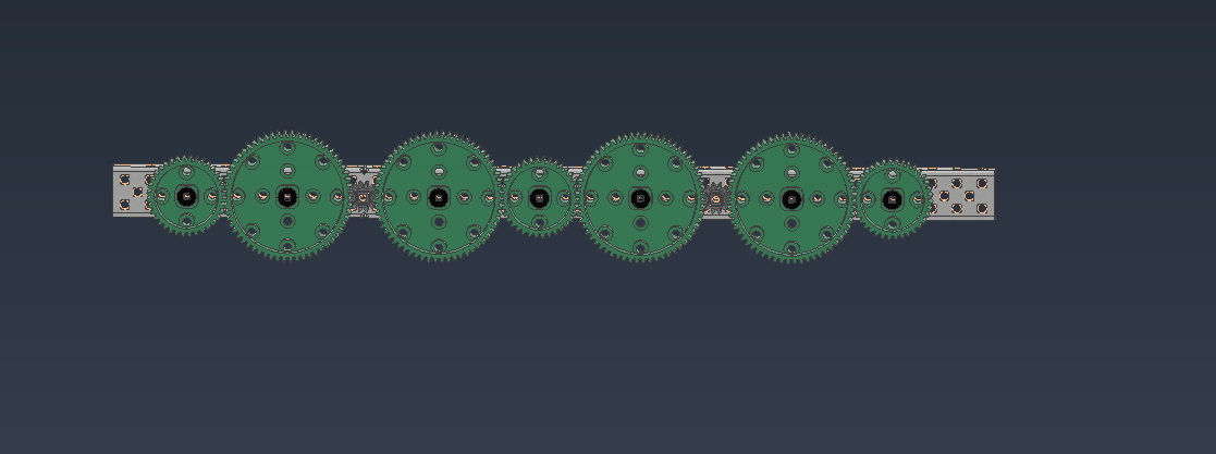
So here’s what our potential drive train would look like -
(wheel and 36T gear) + (60T gear and Motor) + (36T gear and wheel) + (60T gear and Motor) + (wheel and 36T gear)
This reaches the desired RPM with minimized gears and friction but is too clumped together and doesn’t stretch over the full span of the chassis. The drivetrain is very central and doesn’t take up the full space allotted for the chassis.
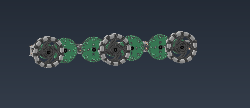
What we wanted to do to take up the right amount of space is add 1 36T gear on each end of the chassis to stretch it out. What ended up happening is that the wheels are now going in separate directions (the front and back wheel are going one way, but the middle wheel is going the opposite way.
We decided to add 1 more gear on each end of the chassis but it’s elevated higher up to not take up much more space but to change the direction of the back and front wheel so that the back middle and front wheel all move synchronously like Sequam Robotics bot (attached). IMG_5372.pdf (2.7 MB)
This would all be avoided if we had 600 RPM motors and idk what to do
Regarding a high quality drive, there have been two threads created by @Xenon27 already. I can’t find the link as of right now, but if you search quality drive in the search bar, it should be one of the top options.
In these threads, the OP explains their choice of drive, engineering and deisign process, as well as some renders.
I would suggest taking a look at those for some inspiration.
An option could be to do a shorter geartrain in the back of the robot, and then do a free spinning wheel in the front. You can see this on one of 1961z Riptide’s bots for Change Up:
62A’s CU reveal:
and 2616J CU:
This is an easy way to extend your base without adding an obnoxiously long geartrain, at the cost of your front wheel not being powered.
It looks like they pulled it off pretty well. They were using 2.75" omnis, while it sounds like you are using 3.25 omnis. That means that they had to spread theirs out further than you will have to.
30 holes is fine, our first design was very little tho. We want some space in the front so that we can cut a little bit of the c channels off and create a dustpan like shape to allow more discs to get picked up where the intake is.
This design is great, but I’m not sure it gives us that space in the front.
But thank you so much for this design tho, it’s currently our best (and only) design that meets most of our needs.
We felt that with more spread out wheels, the robot would perform better and would have better distribution of weight but we may be wrong!
Also, this still has the 9 gears issue right. We would be willing to spread the wheels out less as long as it still has a good distribution of weight if we can get it in 7 or less gears. Any ideas?