That should be fine. I’d be more worried about the pivot joint. It’s worth mentioning that my latest version uses 90° angle gussets to give the encoder more than one support point. I was a bit worried about it twisting over time when I had it on just one, though there was no experimental basis behind the choice. I just wanted to be safe.
oh yea do you have any suggestions to make the pivot joint better?
Well for one thing use bearing flats. I’d also be wary of supporting it on just one side, though if you can make it work then more power to you. I’d also slip a teflon washer in between the 2 parts of the pivot to reduce friction.
If you are using a screw for a joint like that, I’d look out for the c channel bending. Though it shouldn’t be a problem in theory because the nylock isn’t on very tightly, I’d still put some kind of support on the inside of the c channel to make sure it doesn’t bend.
Where are you bearings on each side? If you’re going to be doing that, I would recommend a bearing on each side of the omni, with the encoder loosely screwed on to a screwjoint (it helps reduce friction).
You obviously need a bearing on the plain side, but we were perfectly fine without one on the encoder side. As long as the encoder is screwed in tightly and aligned correctly you don’t need one, and it really helps keep everything compact. For reference, after a plane ride in which our bot was taken out of the box and put back in diagonally, without padding (thanks TSA), they still free spun for 10+ seconds. Not quite the 20 you should get from a 4" drive wheel, but more than acceptable imo, especially on a smaller wheel (we used 3.25", but I would have preferred 2.75" if we had them).
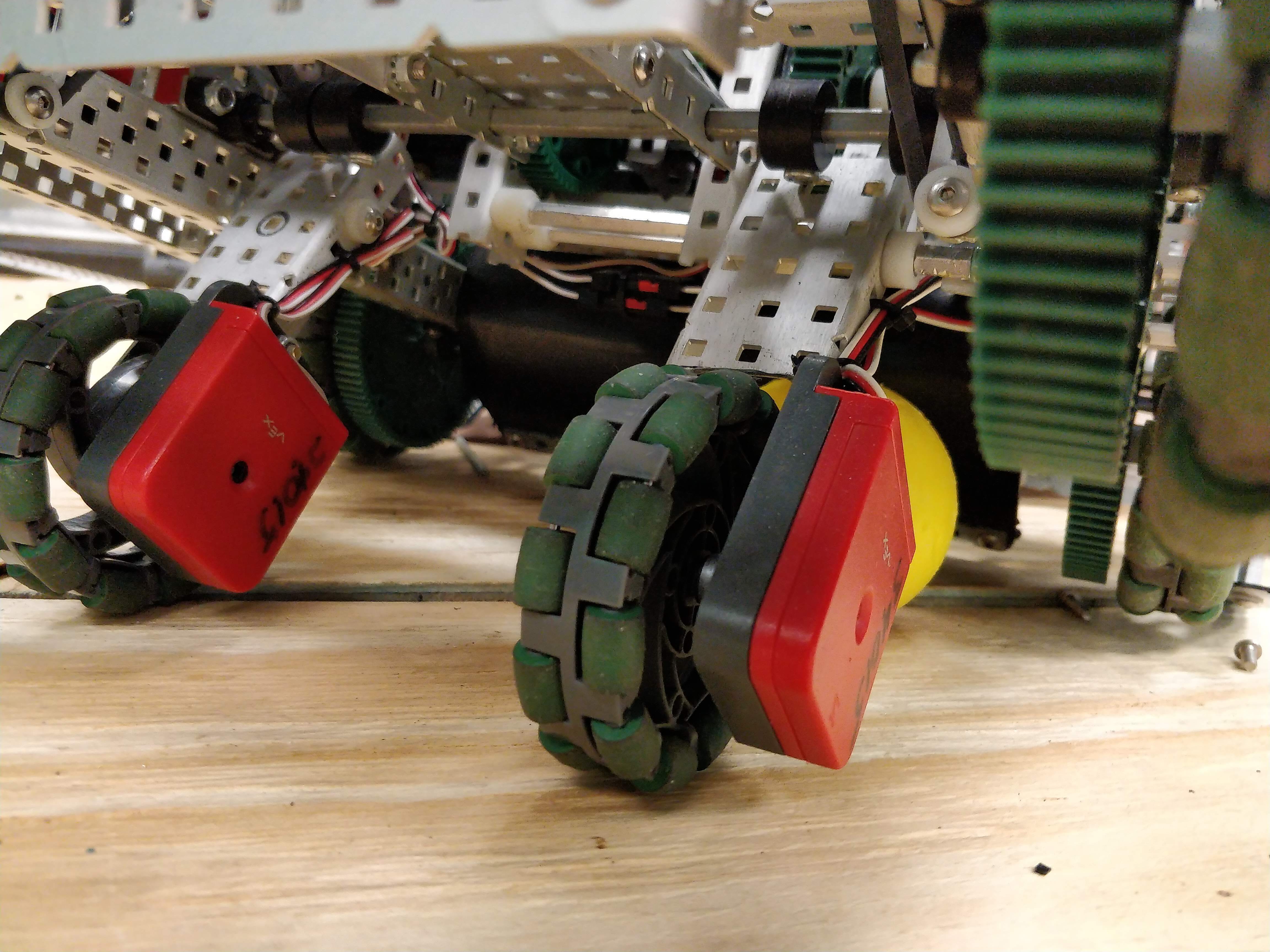
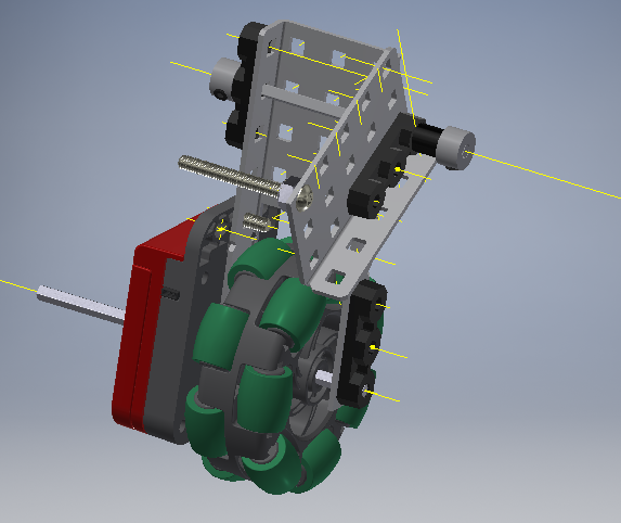
(this image was taken halfway through building)
Hey could someone help me figure out a way to redo the joints because today at school i looked for big enough screws to fit through the 3 bar and couldnt find anything, so the screw idea is gone. I just cant think of anything so any ideas would be helpful.
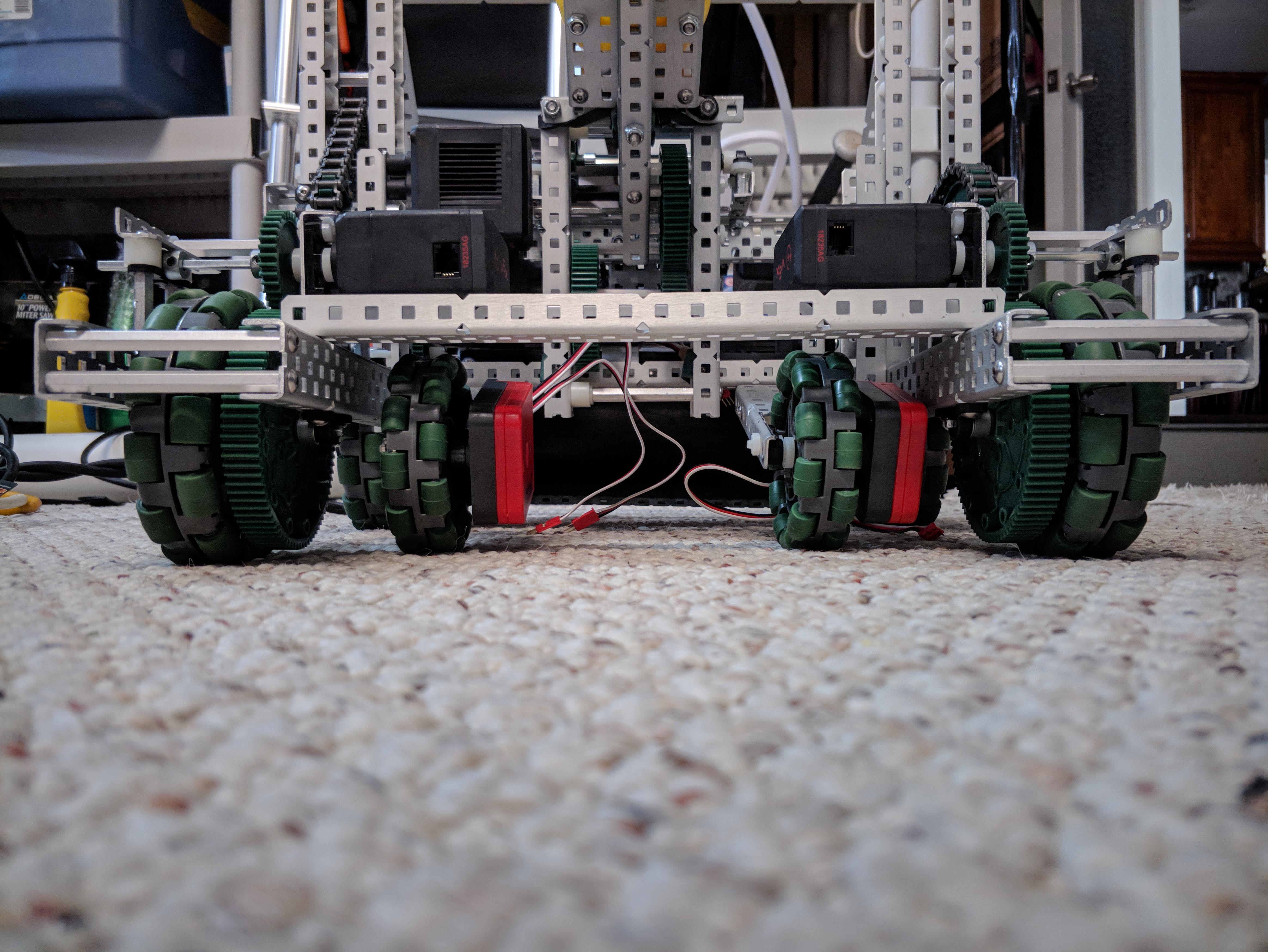
Heres a pic of what i have currently:
Thanks
I mean, you could just do an axle with beating flats there.
You could also use a shorter screw through one side, attach it to a standoff inside the channel, then run another screw through the other side.
I would suggest not using the thick 2.75 Omni wheels but the thin single roller omnis instead. In my experience, the arc length is not best mapped out by such a large contact area, and there is a lot of error that could potentially arise from such a setup. It also adds to the benefit of not needing as much space with the use of 2x c channel. Along with that, the shallower the angle to the ground, the more likely it is to bottom out to the other side with jumps, and the steeper it is, the more the force directs to the ground as well, making it less likely. You would also get more vertical tolerance that way.
I don’t think you can get those wheels anymore
Single row omnis don’t appear to be available anymore. I’ve never seen one in person, and didn’t know they existed until this thread. Maybe removing one row of rollers would be enough to get the desired result? That would also thin up the assembly somewhat without destroying the wheel.
Since i am not able to cut the 2.75 inch wheels in half my only two options that are left are to either use full 2.75 inch wheels or use the 3.75 inch wheels. Which one do you guys suggest to use?
I do not believe there is any benefit to using larger wheels, so the 2.75"
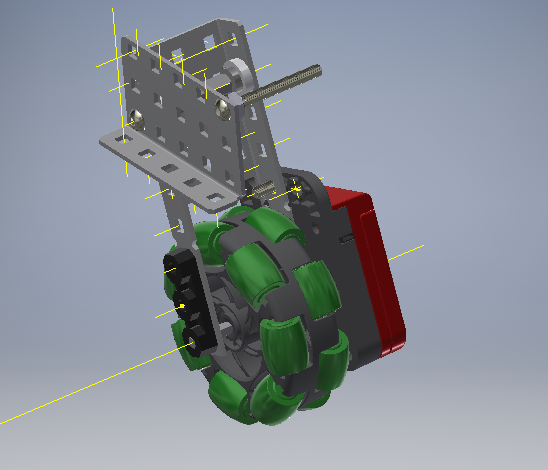
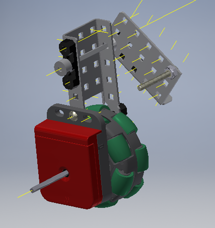
ok cool thanks, so with the 2.75 wheels and a different joint, how does it look, what problems could occur? @ZachDaChampion @P_Mania @ranOOm
and the other side
Hmm…
I’d still be a bit worried about cantilevering the pivot. With so few support points I’d be worried about slop. As such, I’d look into a screw joint with less slop. I’d use the one where you use a nut to tighten the screw onto the support then use a looser nut to hold on the pivoting part.
Also eww… hex bolts…
The thing with the screw joint is that i dont have long enough screws to go through the 3 bar.
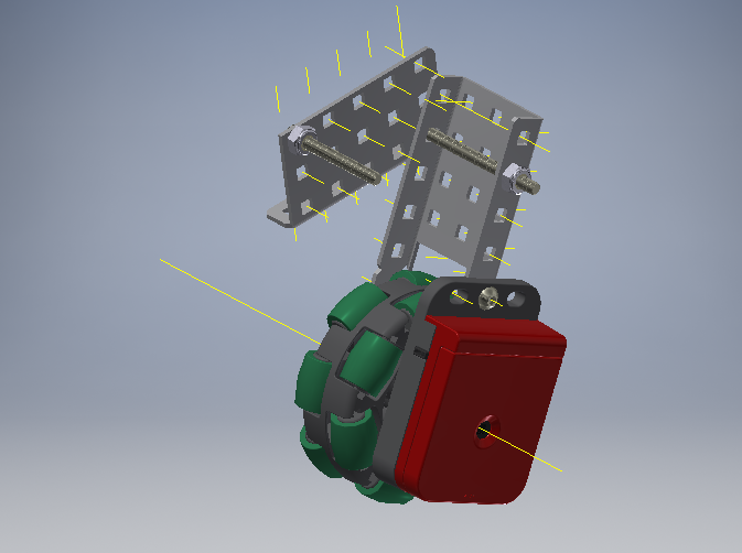
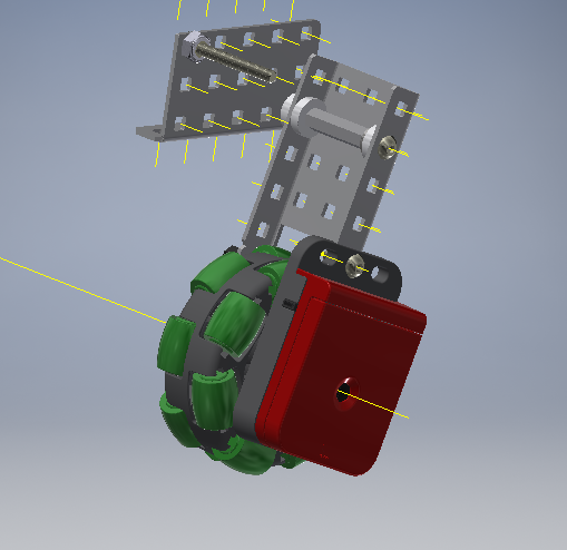
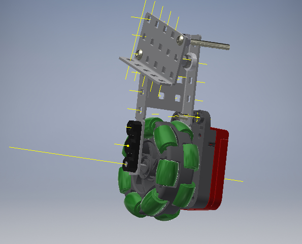
So i made two different joints for the tracking wheel mechanism and i just wanted to know what opinion you guys had, as in which one is better, pros and cons etc.
Screw/Standoff joint :
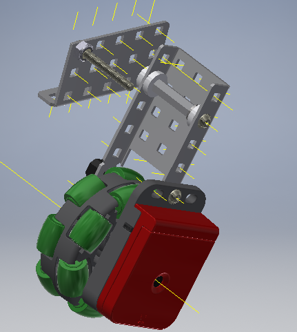
and
Axle Joint:
and
btw the 3 bar looks tilted but is actually straight.
all opinions are appreciated
thanks!
I’d use the screw joint. Axels tend to have a lot of slop when used like this.
This video gets thrown around on this forum quite a bit, but if you haven’t seen it then do take a look. It shows the type of screw joint I was describing earlier.

One last thing: don’t forget that hinges exist. They might not work for your purposes, but if they do then I’d suggest you try them out.
@P_Mania were you describing the Single Bearing Screw Joint? And the only problem that there is, is that I dont have long enough screws to do that. So I dont know what to with that ?
Why not just have two joints?
Like support it on the other side of the C-Channel so it’s not cantilevered and mirror the screw joint.
If you’re using a stand-off in the middle then just use it to join 2 screws. With some lock-tite it should work just fine.