We have a problem with our drivetrain. In straight motion, we’re using a well coded, well tuned PID controller. The problem is it always deviates to the side when we run the program. We’re pretty sure it’s not a programming issue because we’ve been told our pid doesn’t seem to have any flaws in previous threads. So we think it’s a hardware issue. We made sure that there wasn’t any friction on the wheels. We checked if the spacers were correctly put. We replaced the wheels with different ones to make sure it’s not a wheel issue. But nothing works. Do you guys know what could possibly be causing this problem?
Thanks!
It’s probably still an issue with the friction in your drive. if one side has even slightly more or less friction than the other, the wheels on that side will start and stop with different acceleration than the other side, which causes the issue you describe. Try disconnecting the shafts from your drive motors and freespinning the wheels. you should be able to tell if one side freespins for longer than the other.
Sometimes it is actually the shaft going into that motors that is the problem. (this assumes that you are using a geared up/chained up drivebase). That was our biggest issue
How significant is the deviation? If you have it drive forward 4 feet, how much lateral movement is there?
The issue is most likely acceleration as Xenon said. You could try implementing slew rate to reduce the effects of this on acceleration. Decelration should be fine since you are using PID control.
If the robot only pulls slightly sideways, it could be the slop in the motor causing the wheels to start turning at different times
Yes, checking for extra friction on one side, as others said, is first thing to do.
The second question is: do you have a second PID loop to keep it driving straight in software?
If you have well tuned 2-DOF PID controller, then you can disconnect one of two motors on one side and it will still keep the robots driving straight.
If friction on both sides is the same then accumulated Integral value for the second controller is going to be around zero.
But if you print it to LCD and see it walk away from zero - that will tell you that one side has more friction or some other issue.
Small % chance of this being this if you’re a new team: what configuration of wheels are you using? New teams sometimes don’t realise yet that omniwheels in an H drive for tank steering don’t stop sideways drift due to tiny slopes and bumps. Push the robot sideways and you’ll see. Fix that by replacing either both front or both rear wheels with rubber wheels. Your new turning centre will be directly between the rubber wheels. Mecanums in H for tank drive do constrain sideways drift, but they take up a lot more space. Omniwheels in X drive (so that’s at 45 degrees to draw a circle together) also constrain sideways drift and can be driven for tank mode that same way as an H configuration, but you get sqrt(2) more speed. If that’s your problem, welcome to the holonomically woke! If not, good on you, and I’ll get my coat…
When we see the number of revolutions that each motor does, the motor in the right spins more than the one in the left. But one we put the robot on the field and run it, the robot turns to the right. That’s just plain frustrating and we can’t figure out what’s wrong.
And we’ve tried replacing the motors by other ones, changing the ports and the cables. But whatever we do, the motors we put on the drivetrain start doing a different number of revolutions.
While technically correct, this is bad advice. A 4-wheel Omni drive is superior in almost every way to a split traction/Omni drive.
Yeah, but you can kiss your pushing power goodbye.
Assuming that the gearing, motor cartridges, and wheels are mirrored, the only way the right side motors can turn more while having the robot turn *right is if somethings slipping, and that could be internal (gears skipping, axles slipping) and/or external (wheels slipping on the tiles).
Does it deviate to the side if you just set the drive to full power forwards without PID? If it’s constantly turning then as well then there is definitely a friction issue. If it only turns during the initial acceleration it could also be a problem with wheels slipping on the tiles.
Not quite, because for the robot to turn left, the right side actually has to cover more distance than the left side. Also I think the op would notice if they have gears or shafts in their drive slipping, and if they do they probably have bigger problems than just a slight sideways drift. Wheels skidding on the ground can cause these sorts of issues, but if the acceleration of all 4 wheels is the same, and the center of mass of the robot isn’t off to one side, one half of the drive shouldn’t skid significantly more than the other.
What’s more likely is just friction variance on one side causing the wheels on that side to accelerate faster or slower than the other, which will cause a bit of rotation as the drive starts to move. Additionally, if the friction is very significant one side could have a lower top speed than the other, and that would make the robot be constantly moving in a very wide arc.
the best way to solve this sort of issue is to first try and reduce friction as much as possible with the entire drive. A big point of friction is when a shaft goes through two bearings that might be ever so slightly mis-aligned due to the slop in vex holes. Make sure that all shafts can free spin easily before tightening down the frame of the drive. Pictures would probably help us assist you in friction reduction. And if you still have an issue with not moving in a straight line, you can use an inertial sensor or get your heading from tracking wheels and correct your robots path to stick to the same heading. However, I believe that a mechanical problem should be solved as much as possible by mechanical means, so I would highly advise you first try to reduce the issue by reducing your friction.
a 2 motor drive will inherently be weaker than a 4m drive, so friction will impact it more, but if built properly it shouldn’t be the issue.
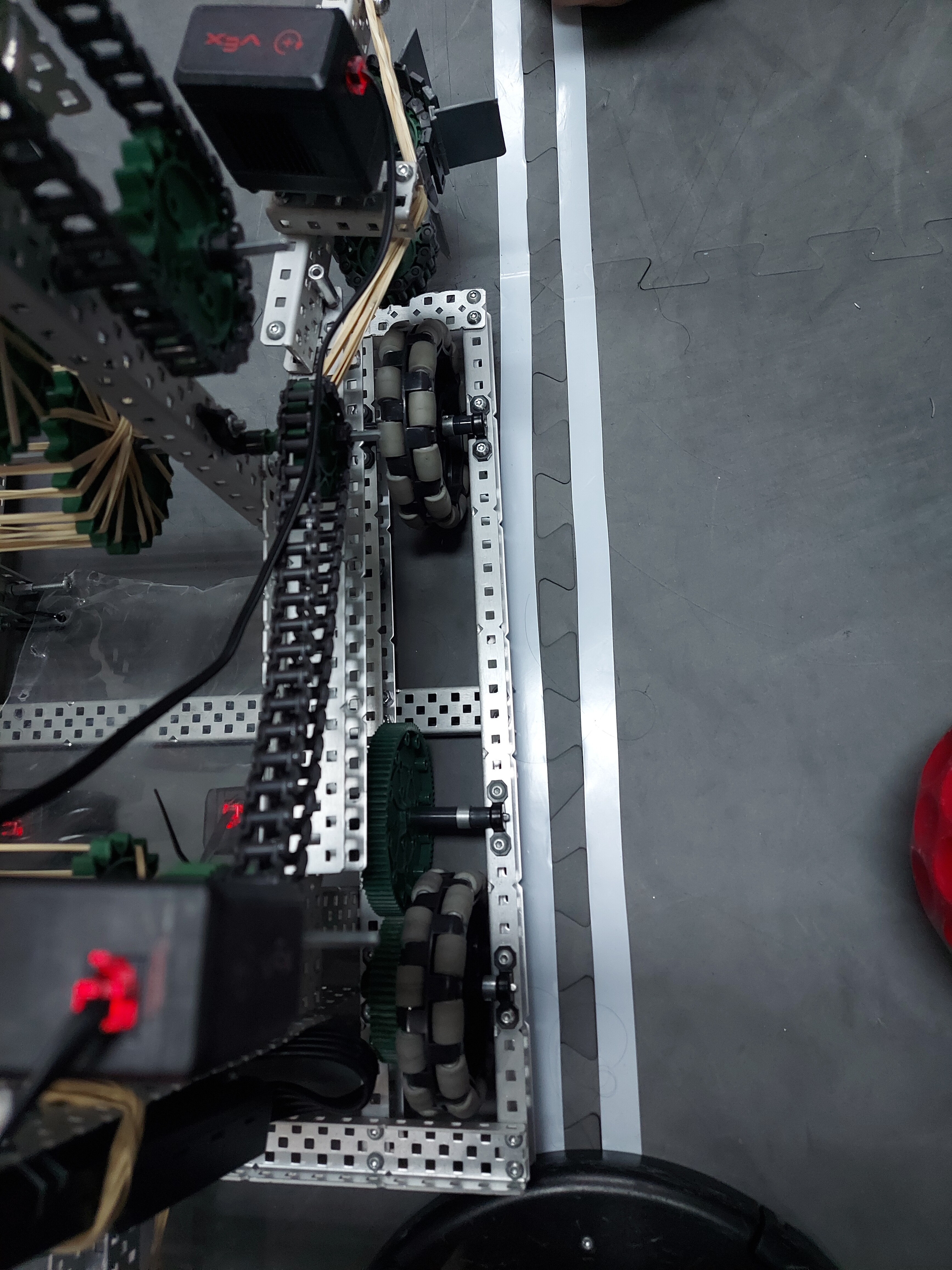
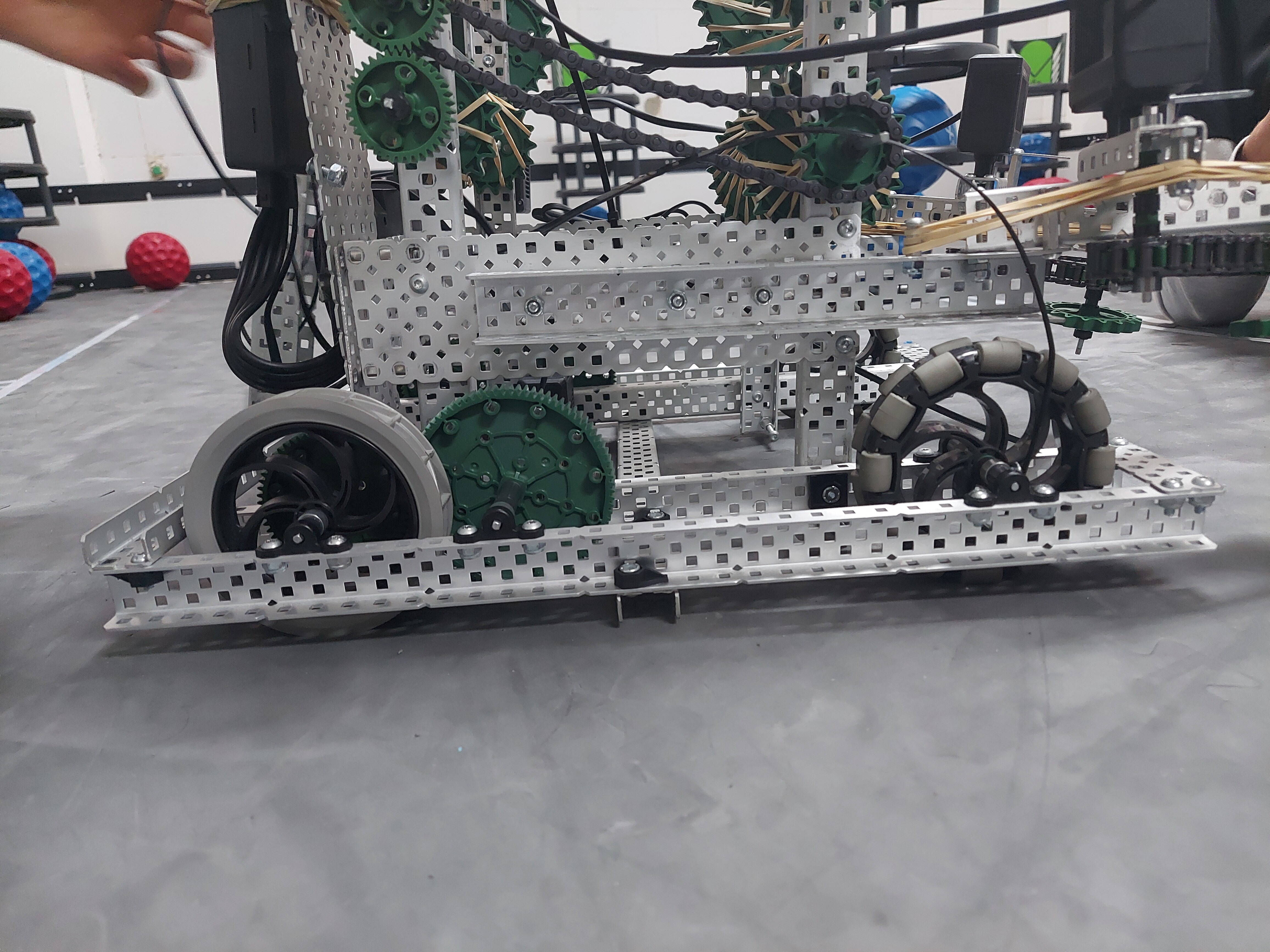
I’m kind of confused what I’m looking at here, I see what looks like a 1:1 ratio connecting your back wheels, and your front wheels appear to be linked somewhere with chain, but I’m not quite sure where.
Also, this may be from the perspective of the photo, but to me it doesn’t look like your shafts here (especially the back two) are perpendicular to the c channel on your drive, due to the inherent slop that screws have in holes. This would cause significant friction.
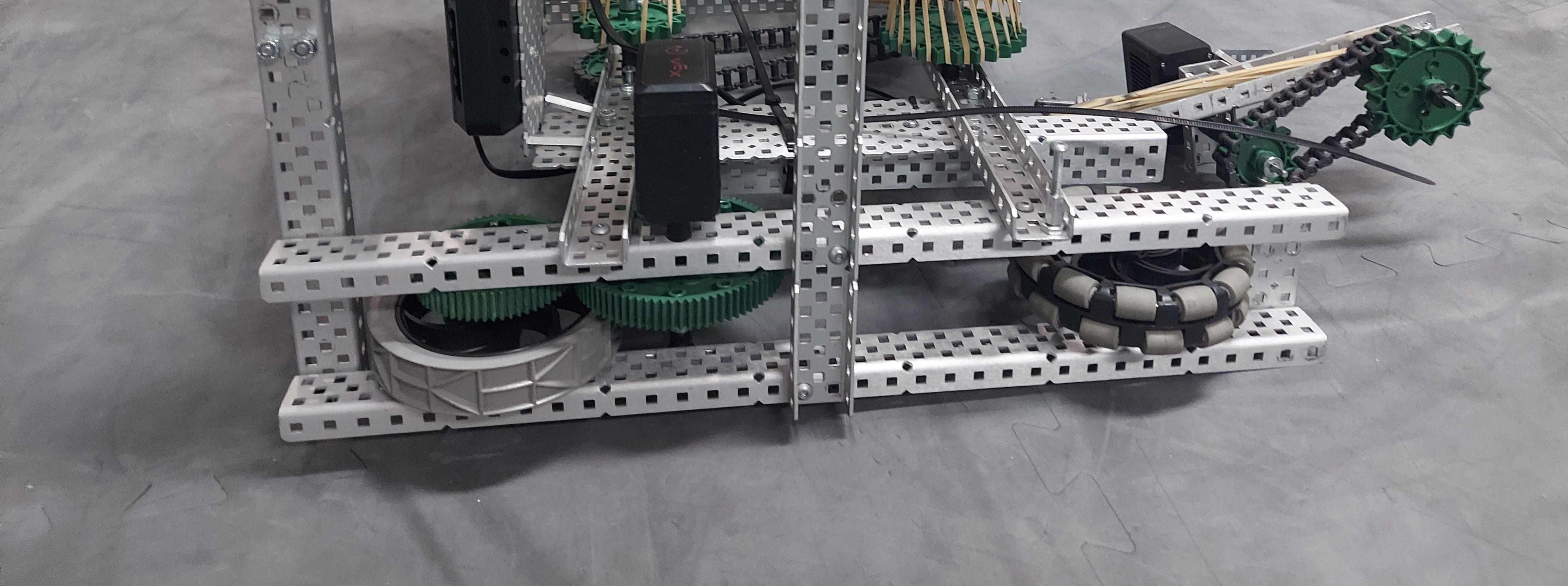
Do you have any better photos that could show how the whole drive looks? perhaps an angle from the underside?
Also that’s true that the c channels weren’t really perpendicular. We fixed that though but we still have the problem.
So it’s a 7:5 ratio two wheel drive, with only the back wheels getting powered.
is that a 200 or 100 rpm cartridge motor?
I can see that the two sides of your drive aren’t quite aligned properly, which is probably the source of your issue. I also notice you only have one screw holding that central cross beam to each side of the drive, you really should have two screws here because having only one point of contact creates a pivot, which made it much easier for your drive to misalign.
Also if those motors are 200 rpm cartridges, a 7:5 ratio with only 2 motors is very aggressive. That would have the equivalent torque of a 560 rpm 4 motor drive, so essentially nothing. If you can, adding two more motors would likely reduce the impact of friction by a great deal, and just improve your overall acceleration and torque.
Ah whoops typo, meant turning right not left
Just in case you haven’t check to make sure both drive motors have the same cartridge, this is the only way I can think that one side would spin faster without load, but not accelerate as quick with load.
Manually turn either side of the drive and see if one is harder to move than the other.