Is there an example of VEXCode V5 Blockly for honomic smilar to this I found for robotmesh?
Yeah I’ll get my hands on an example from our code
Thanks! I appreciate it.
You’re looking for VEXCode v5 Blocks equivalent code, right?
Yes VexcCode for holonomic control
VEXCode v5 Text or VEXCode v5 Blocks?
VexCode Blocks
Thanks
Looks like the screenshot is based on this public RobotMesh example:
https://www.robotmesh.com/studio/5be40c8ac8f17a1f5796cf57
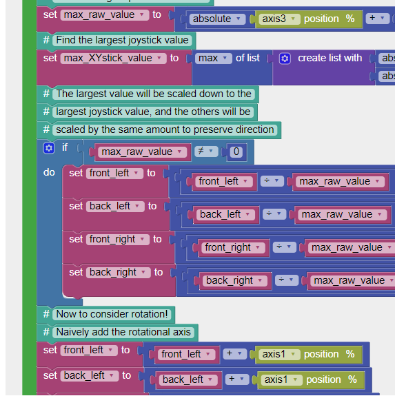
Tried to stay true to the example and and not to deviate what they were doing. Didn’t have an Holonomic X-Drive to test out. So there are probably errors in it, but it’s a start and anyone with an X drive can troubleshoot and fix: Holonomic.v5blocks (42.3 KB)
I cannot get it to open. ![]()
It says it used a newer version. I updated and restarted. Still cannot get it to open??
Can you screenshot it?
It was created in the latest VEXCode v5 Blocks.

It can export a PDF, that will include all of the blocks. Holonomic.pdf (29.4 MB)
Ah this was VEXCode for Iq.
I was trying to open it in VEX Code for V5.
Thank you very much.
How do I create the the 1 ,2 ,3 ,4 position on controller’s joysticks in VEXcode IQ Blockly?
I always stuck at those button settings and I could not jump to the joystick setting to define the 1, 2,3,4 axes!
I think this Knowledge Base article may help answer your question. It includes the position and names of the left & right joysticks:
Thank you so much for the information and I am doing this on the VEX IQ except the V5 system. That’s why i saw different naming rule in the VEXcode^^
I have check the code and I am really confused about the minus “-” on the joystick axis 1. I think joystick axis 1 should refer to the axis of rotation. If so, why there are two minus “-” on the joystick axis 1 for both the setting of front_right and back_right motor? I would be very appreciated if you could give me some instruction about that
I’m not exactly sure what you are asking so I’m just guessing.
The example that @gbr posted has some bugs in it based on order of operations. (I didn’t look further than the controller lines.)
The general code for holonomic is
LF = VSpeed + HSpeed + Yaw
LR = VSpeed - HSpeed + Yaw
RF = VSpeed - Hspeed - Yaw
RR = VSpeed + HSpeed - Yaw
However, block code only has two operand assignments: (a + b), (a - b), etc. The three operand assignments need to be grouped correctly to get the right output value. Using V, H, & Y for the equation of LR could have two groupings V - (H +Y) or (V - H) + Y. The first one is not the same as the base equation above. But the second one is. Just make sure you group the first two operands and leave the third one on its own. Note that this is what the RobotMesh example does.
Thanks for the sharing of the definition of Holonomic general code and I will check it out!
What I meant to the axis of rotation should be in the same direction is based on the youtube video by Doug Klein regarding to the VEX Holonomic below. I think I do need to figure out what’s the difference between these two definition about the rotation axis
VEX Holonomic Drive by Doug Kleig

The difference is that the equations I posted are for the drives with left motors normal rotation and right motors reverse rotation. Right reversed is typical for skid steer which is most often used drive. Doing this makes the holonomic equations look similar to skid steer arcade.
The equations from the link are for all motors set to normal rotation.
Please take my sincere appreciation for the clear and simple instruction!
You’re welcome.
Also of note is the link shows x-y control on the right and yaw on the left. But the robotmesh code and I think most other code have x-y and the left and yaw on the right.
As you get more advanced here is a link to a different way, from robotmesh, to code x-arcade so the input values from the controller don’t exceed the motor range.