This will be a 3-part post:
- Turing a bot to a heading.
- Driving forward/reverse on a specified heading for a given distance.
- Driving forward to an object using a specified stop at distance.
Part 1: Turing a bot to a heading.
Theory
Heading (in navigation), is defined as the compass direction in which the craft’s bow or nose is pointed. Note that the heading may not necessarily be the direction of the vehicle, which is known as its course. For example, if your bot is on a heading of 15 degrees moving forward and starts going in reverse it is still on a heading of 15 degrees.
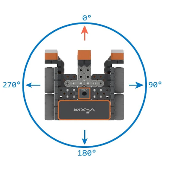
A heading is given in degrees (0-359.99999…). Note that there is no such thing as a heading of 360 degrees this is in fact a heading of 0 degrees.
A change of heading is also defined in degrees. However, here the value given is to be added or subtracted from the current heading. For example, a change of heading from 0 to 90 degrees would be a 90-degree right hand turn of the bot. In robotic navigation we need to know two distinct headings.
- The current heading
- The desired heading
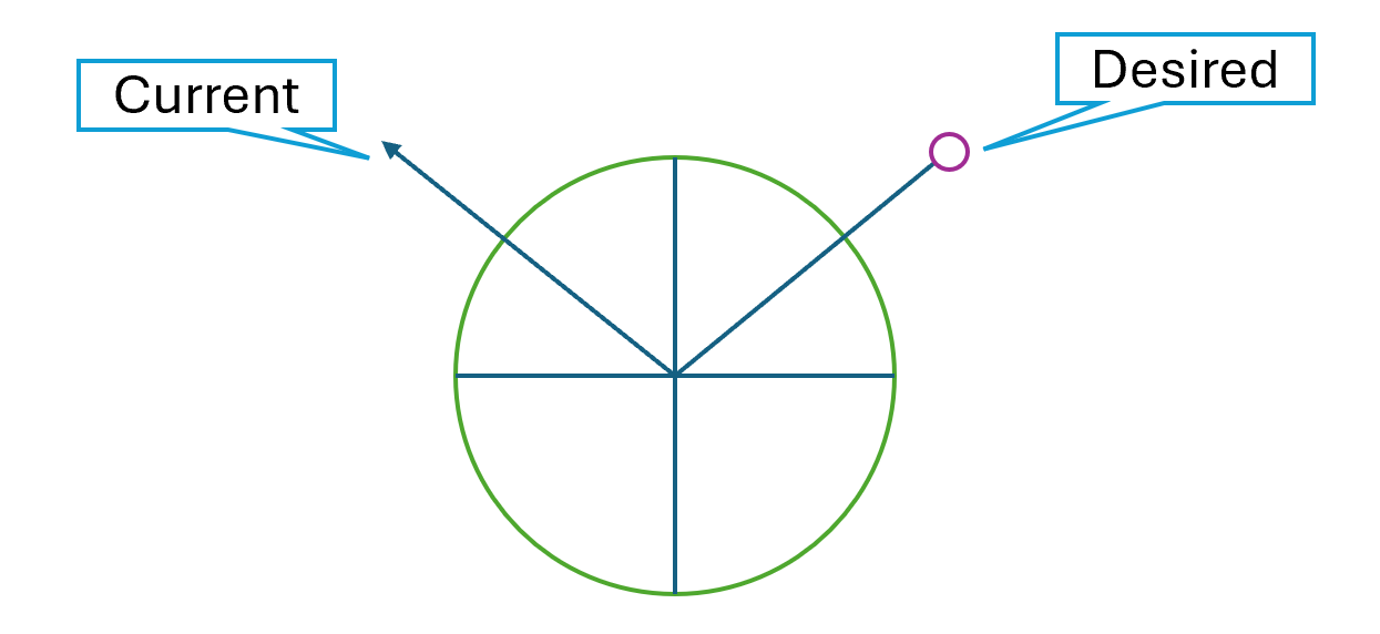
In this post I will use an arrow to represent to current heading and a “lollypop” to represent the desired heading. The Block definition provided in this post will direct the bot (in a stationary position) to rotate about it’s turn radius until the bot heading reaches the desired heading. If the bot design has a zero-turn radius, it should in theory not move from its current position during the action.
The actual turning is accomplished by instructing the right and left drive motors to turn in the same directions at the same speed (RPM). More detail on this will be provided in the code explanation.
One challenge to developing this code is finding the rotational direction which will get you to the desired heading in the shortest period of time. To do this we will use the following algorithm.
-
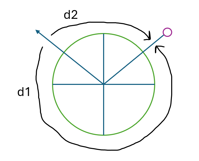
Determine the two possible angular distances to rotate the bot as illustrated below.
Here:
d1 = abs(Desired – Actual)
d2 = 360 – d1Although from the illustration it is easy to see that d2 is the clockwise
(CW) distance and d1 the counterclockwise (CCW) distance,
programmatically this is not yet known. Step 2 of algorithm is used to
determine which distance is CW and which is CCW. -
If the current heading is greater than the desired heading, d1 is CCW and d2 is CW. If the current heading is less than desired heading, d1 is CW and d2 is CCW.
I will leave to the reader to prove out this algorithm for themselves. Hint look up the mathematical definition of absolute value between two point on a number line.
To move a VEX IQ bot programmatically you must first ascertain a few facts about your bot.
- The wheel circumference.
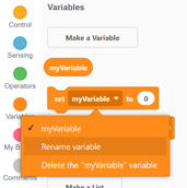
- The Input to output gear ratio on the drive wheel.
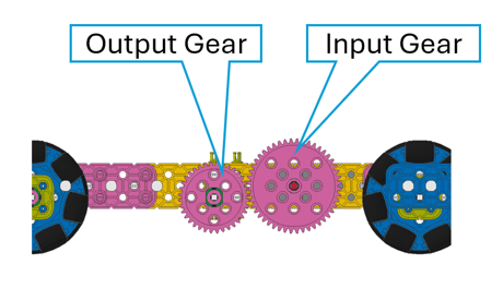
- The distance between the right and left drive wheels.
In the code we will capture this information in the form of constants (see my post “Using 2 TouchLEDs to select an autonomous routine, start the routine, and stop the routine mid-way.” for a definition of variables in block code).
Let’s get started. First you will need a working drivetrain with a right and left side drive motor. If you wish to build the drivetrain I used to develop this code, here are the Snap CAD files in a zip.
CAD Drivetrain.zip (4.4 KB)
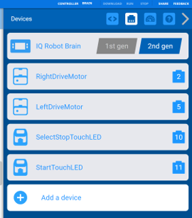
In VexCode IQ start a new project titled “CustomDriveV1.0”. Once the IDE finishes creating the blocks project add the right and left drive train motors as shown below.
Next add two TouchLEDs to your bot. The devices configuration should look as shown below.
Now we need to know which motor to reverse to prevent the bot from spinning when we ask the bot to move straight. I will leave it to the reader to figure out why that is. Hint check out the rotational direction of the right and left motors in the bot.
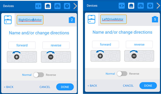
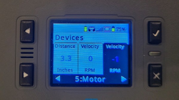
To discover which motor to reverse use the devices interface on the brain. Select one of the motors and spin the wheel forward. If you are unsure which way to turn the wheel just place the bot on a smooth surface and push it forward.

Which ever motor show a negative RPM (see image below) is the motor which needs to be reversed. On my test drivetrain the motor on port 5 needed to be reversed.
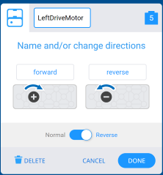
Open the port configuration in devices blade (as shown below) and click on “Reverse”.
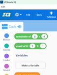
OK, it is time to write the application set up code. You will need to add a few global variables and constants using the “Make a Variable” button. This button is found in the blocks blade on the left of the IDE.
If this is a new project you might have the “myVariable” variable. If so, just rename it to “IN_GEAR_SIZE” as show below using the “Set” blocks drop down and selecting “Rename Variable”.
Using the “Make a Variable” button add the following constants.
-
IN_GEAR_SIZE (if not already done) – Used to hold the size of the drive gear on the motor shaft known as the input gear.
-
OUT_GEAR_SIZE – Used to hold the size of drive gear on the wheel shaft or output gear. If you have any gears in-between the input and output gears ignore them.
-
DRIVE_BASE_WIDTH - Used to hold the distance between the left and right wheels. Measured from center left to center right wheel.
-
WHEEL_SIZE – Used to hold the circumference of the drive wheel. Note the size of any other wheels is irrelevant.
-
BOT_BATTERY_LOW – Bot state when low battery is detected.
-
BOT_READY – Bot state when bot ready to select or run a routine.
-
BOT_RUNNING – Bot state when bot is running a routine.
-
ROUTINE_NONE – Used to indicate no routine selected.
-
ROUTINE_1 – Used to indicate that routine one has been selected.
-
ROUTINE_2 – Used to indicate that routine two has been selected.
-
HEADING_TOLERANCE – Used to hold the largest acceptable heading variation.
-
MIN_VELOCITY – Used to hold the smallest RPM motor setting which will keep the bot moving.
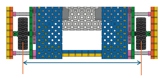
Place “set” blocks for each of the constants under the “when started” block (event handler) as shown. This will ensure that the constants will only be set once when the program starts. Be sure not to have more than one “when started” block in any program.
Once the constants are in code, we are ready to add a few global variables.
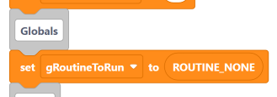
Start by adding “gBotState”. “gBotState” will be set when to battery is checked. Next add “gRoutineToRun” and add the set block under the constants as shown.
We are now ready to define a few blocks in the code. To do this use the “Make a Block” button under the “My Blocks” section of the blocks blade on the left side of the IDE”
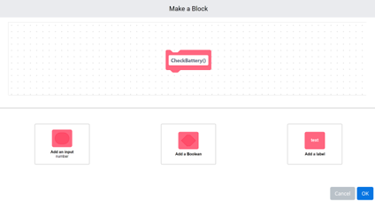
You will add the following block definition. We will leave them blank for now.
-
CalibrateGyro() – Used to calibrate the internal brain inertial sensor which we will be using as a gyro in this code.
-
CheckBattery() – Used to confirm the battery has a minimal charge. For most bots this will be 80% but you will need to determine that in testing of your bot.
-
RoutineOne() – Used to hold the first routine code.
-
RoutineTwo() – Used to hold the second routine code. Note you can add additional routines using this pattern.
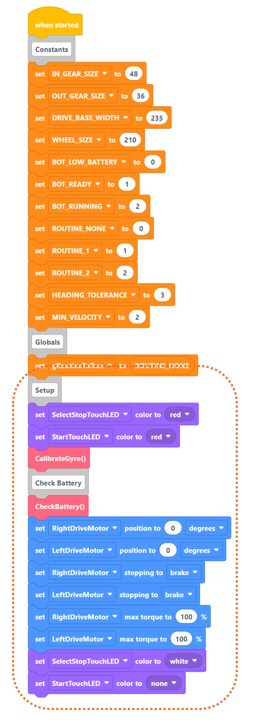
Add the code listed below under the “when started” event handler as shown. Be sure to add the comment blocks.
Code explanation
The “when started” event handler is coded to first set the constant values which will be used throughout the application. The global gRoutineToRun is initialized to none and will be set on the TouchLED “pressed” event handlers to be added later.
Next the handler has code to set the bot LED colors. Here both are set to red, but you can use any color you like. This is to indicate the bot is not ready for user interaction. This includes moving the bot.
The CalibrateGyro block (or method*) is called next followed by the CheckBattery method.
Once the CheckBattery method finishes the right and left drive motors are configured as follows:
- Motor encoder is set to position 0. This is done only for teaching purposes. All motor encoders are set to position 0 when any application is started. In the VEX IQ platform “Smart Motors” have a single optical encoder set on the output shaft (this link will give you a little more information).
- Stopping is set to “Break” this option ensures the bot will stop when the motors are stopped. There are 3 options in the drop down (hold, break, coast). Here I choose break over hold to save the battery power. However, if your bot needed to climb an incline you will need to use hold to prevent the bot from rolling downhill.
- The “max torque” is set to 100% to ensure the motor can reach requested RPM as quickly as possible.
The two touch LEDs colors are now set to indicate the bot is ready for user interaction. At this time the bot can be reset to a new position (even a position which will change the bot heading).
Add the code listed below under the “CheckBattery()” define block as shown.
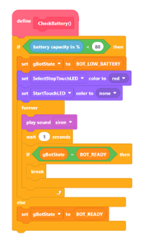
Code explanation
This code checks the battery capacity.
If it is over 80%, the bot state is set to BOT_READY and the method ends.
If not, the follow will take place.
- The bot state is set to BOT_LOW_BATTERY which blocks any other actions from taking place.
- The two touch LEDs colors are now set to indicate the bot is in a low battery state and that the user can override this by pressing on the “red” Led (SelectStopTouchLED).
- A siren sound is played in a forever loop which can only be ended by pressing the “red” LED or shouting the application down.
Add the code listed below under the “CalibrateGyro()” define block as shown.
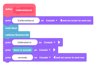
Code explanation
This code does the following:
- Reset the brain timer. This is done to start a timer on how long calibration takes to complete.
- Once calibration is completed the time in seconds (rounded) is written out to the application console. If a calibration take over 2 seconds, it may need to done a second time.
We are almost ready to crate the “TurnToHeading” block (method). But first we need to create a support utility method. When ever code is used 2 or more times in an application it is always a good idea to place this code in separate function or method. If code is repeated in multiple application, it is a best practice to place that code in a separate library.
To create this block (like before) use the “Make a Block” button under “My Blocks” section of the blocks blade on the left side of the IDE.
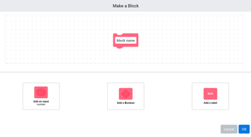
In the block name section type the following.
DetermineQuadrents(Heading[degrees]:

Click on the “Add an input number” button to add the method parameter for Heading. Type Heading where you see number.
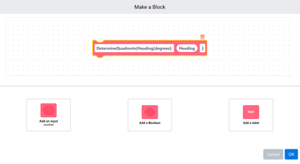
Click on the “Add a label” button to add the closing parentheses to the method.
Although all these steps are not required, it makes it possible to use the block in code without the need to look up what each of the parameters are. In more advanced programming languages this information is provided by intelsence.
Add the block code listed below to your “DetermineQuadrents” method.
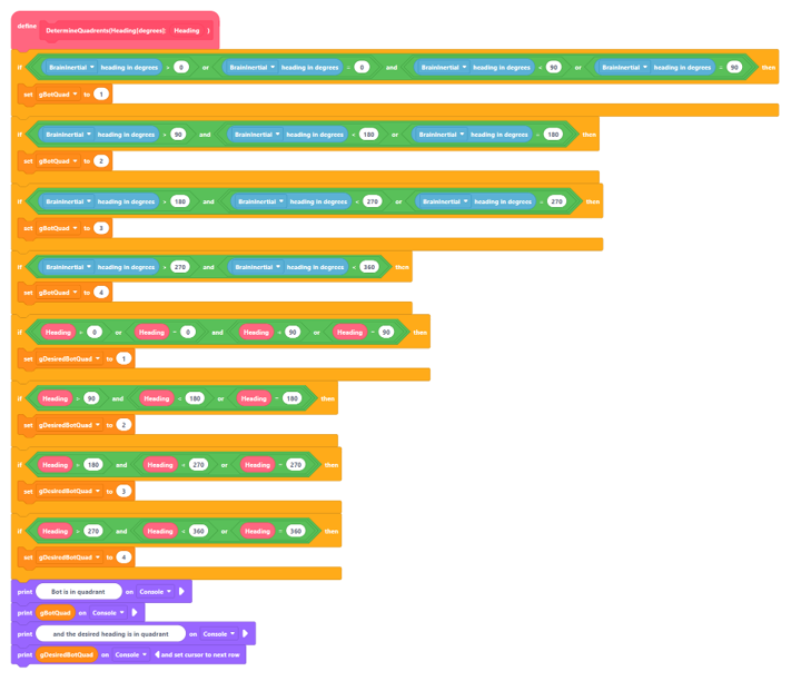
Code Explanation
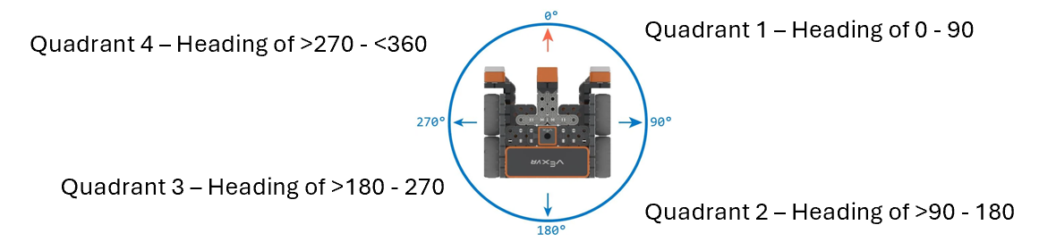
This method will determine which of the 4 heading quadrants (see below) the bot’s current heading is in and which one the desired heading will place the bot. This information is then used to calculate if the current heading is within tolerance of the desired heading. To put it another way, “is the desired heading is close enough to the current heading to work”. If yes, no turn is needed. The heading tolerance will need to be determined through testing of your bot.
We are now ready to add the “TurnToHeading” method to our code.
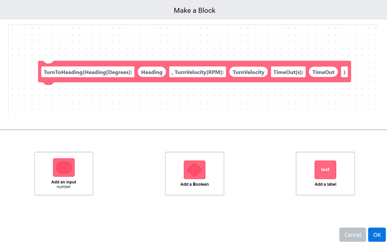
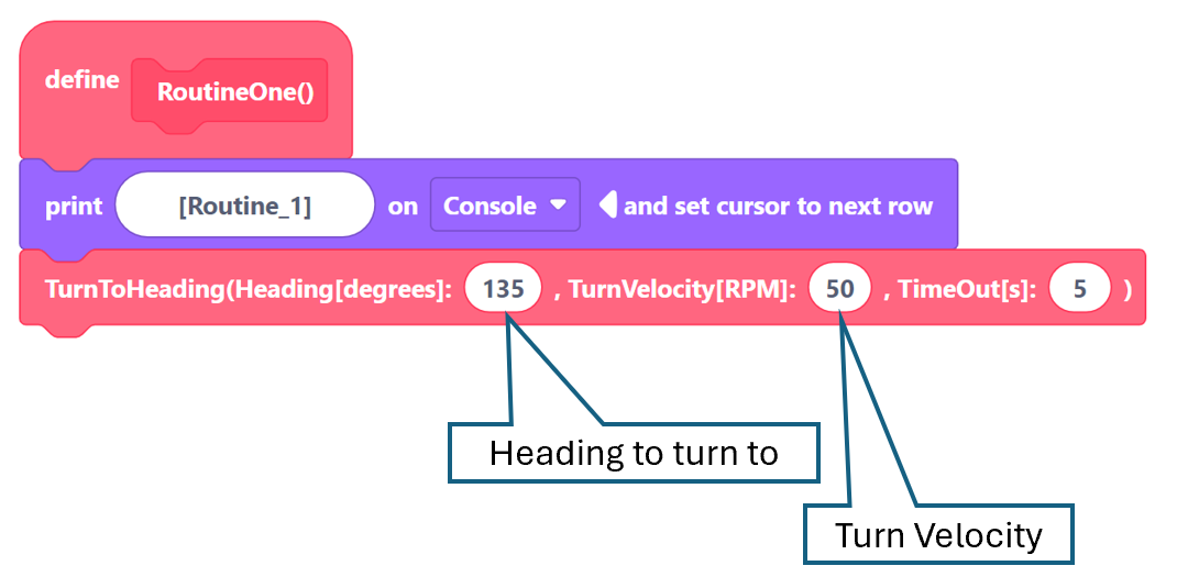
First, we need to add the definition as shown below. The parameters to add are:
- Heading (number) – Used to hold the value of the desired heading.
- TurnVelocity (number) – Used to hold the value of the max. RPM to be used to complete the turn.
- TimeOut (number) – Used to hold the time out value. A time out value is the max. allowed time to complete an action.
Add the code listed below to the define block as shown. We will be building this method one piece at a time.
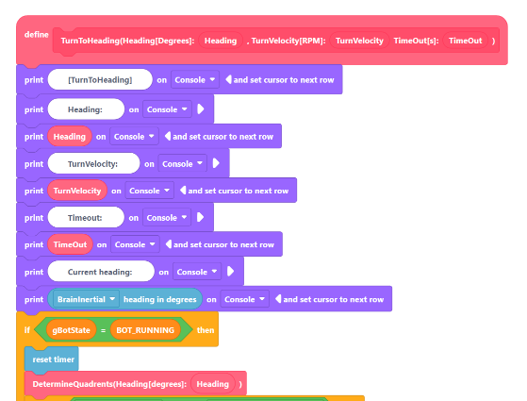
Code Explanation
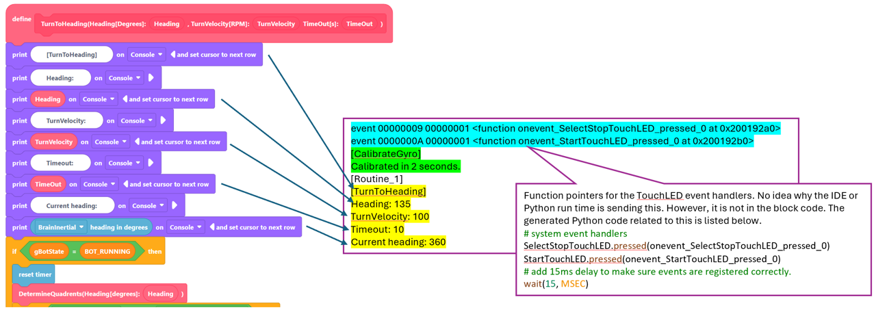
Here the code starts out printing debug information to the console (see below).
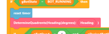
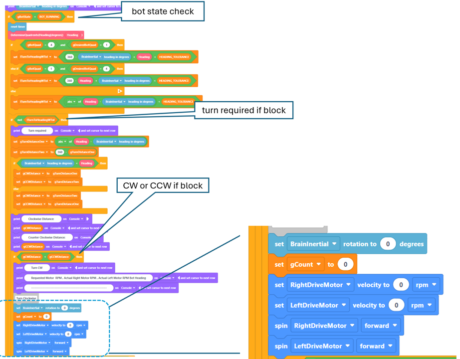
The if block is used to checks the bot state. The bot state must be BOT_RUNNING for the rest of the code to run. Within the if statement are blocks to reset the brain timer and make a call to DetermineQuadrents method.
Add the if-else if block code listed below to the define block under the call to “DetermineQuadrebts” call.
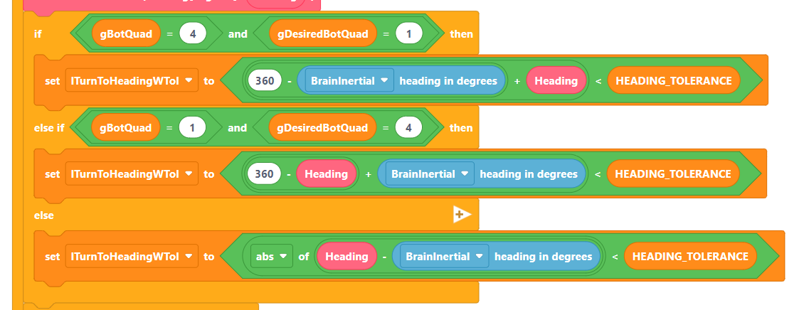
Code Explanation
This code sets up the three different equation used to calculate the delta (difference) between the actual bot heading and the desired heading.
- Actual Heading is in Q4 and the desired is in Q1.
Here the delta = ((360 – Actual) + Desired) - Actual Heading is in Q1 and the desired is in Q4.
Here the delta = ((360 – Desired) + Actual) - All other possible combinations.
Here the delta = abs(Desired – Actual)
Note that a “set” block is used in each to set the Boolean value of the variable lTurnToHeadingWTol. If the condition (is less than HEADING_TOLERANCE) resolves to true, the Boolean variable is set to true. If false, it is set to false. The flow of the code only allows one of these set blocks to be called based on the desired and actual quadrant values.
Add the if block code listed below to the define block under the previous code. Make sure this is inside the bot state check if block.
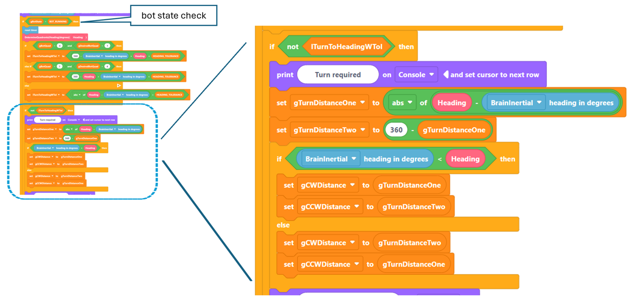
Code Explanation
This code starts with a check to see if a turn is required by asking id the heading delta is within tolerance. If so, the following is done:
- Print debug info.
- Calculate d1 (see theory section)
- Calculate d2
- Decide which distance is CW and which is CCW.
Add the code listed below to the define block under the previous code. Make sure this inside the bot state check if block as before.
Code Explanation
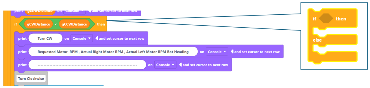
Most of this code prints debug info. The only function piece is the if block used to determine which way to rotate the bot. If the CW distance is less than the CCW distance, the bot will rotate CW. If greater than or equal, it will rotate CCW.
Add the code listed below to the define block under the previous code. Make sure this code is placed inside the bot state check if block, the is turn required if block, and the CW or CCW if block.
Code Explanation
This code will do the following:
- Set the BrainInertial sensor rotation value to zero so that rotational value will represent rotation of the bot during the turn.
- Set a count variable used in the wheel motor speed calculations to zero.
- Set motor velocity to 0 rpm to prevent the motors from starting to spin before the velocity has been calculated.
- Set both the right and left drive motors to spin forward. This may seem to be incorrect given that if we spin both motors forward the bot will move forward. However, we will correct this by setting the reversed motors velocity to a negative value. Unfortunately, the VEX library spins a motor when the velocity is set to a value that is not zero using the sign of the value to indicate direction.
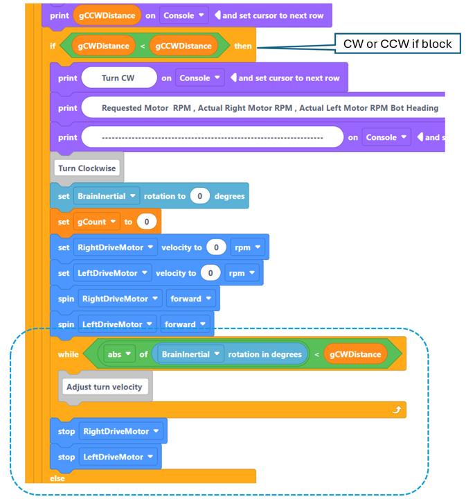
Add the code listed below to the define block under the previous code. Make sure this code is placed inside the CW or CCW if block.
Code Explanation
This code will do the following:
- Setup while loop which will run as long as the bot’s rotation is less than the required rotation needed to reach the desired heading.
- Stop the drive motors once the loop ends.
The sample rate or wait time before each read of the rotation value is not set in the block code but rather in the generated code (see below). Although this is done by the code generator to prevent one thread executing a loop from monopolizing the CPU it has the added side effect of establishing a sample rate which we will need when we are analyzing the code performance.
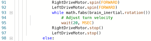
Add the code indicated below within the while loop.
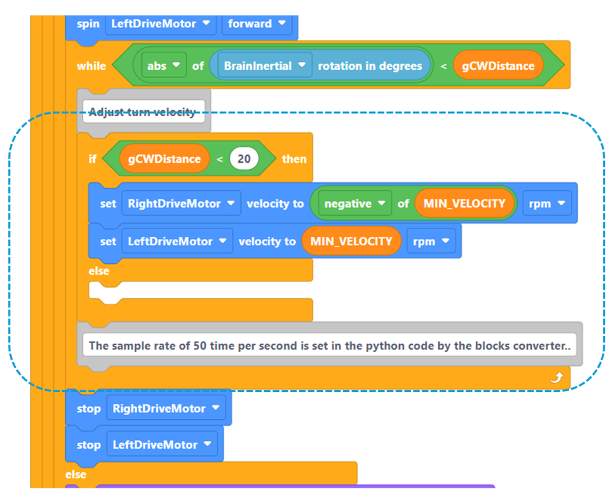
Code Explanation
This code checks if the rotational distance needed is less than 20 degrees (first tunning number). If so, set the velocity to the minimal value which will ensure the rotation does not overshoot. Note that the right drive motor velocity is set to a negative value. This will make the right drive motor rotate in the reverse direction.
Add the code indicated below within the while loop.
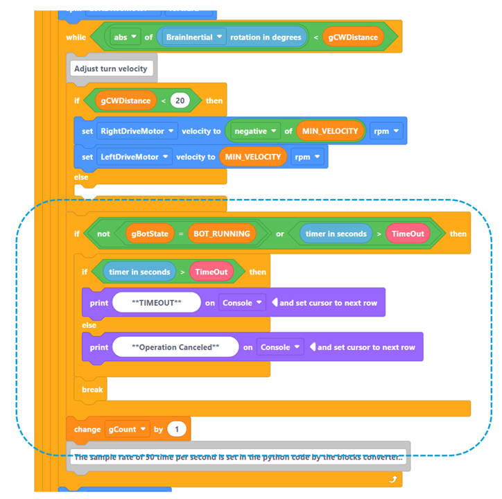
Code Explanation
This code will do the following:
- Check two separate conditions.
a. Has the bot state changed from running. This is how the operation cancelation works.
b. Has the time out value been reached. - If timed out, indicate this for debugging. Otherwise, indicate operation cancelation.
- Break out of the while loop ending the operation and allowing the remaining routine code to run if the bot state is still BOT_RUNNING.
- Increment the loop counter.
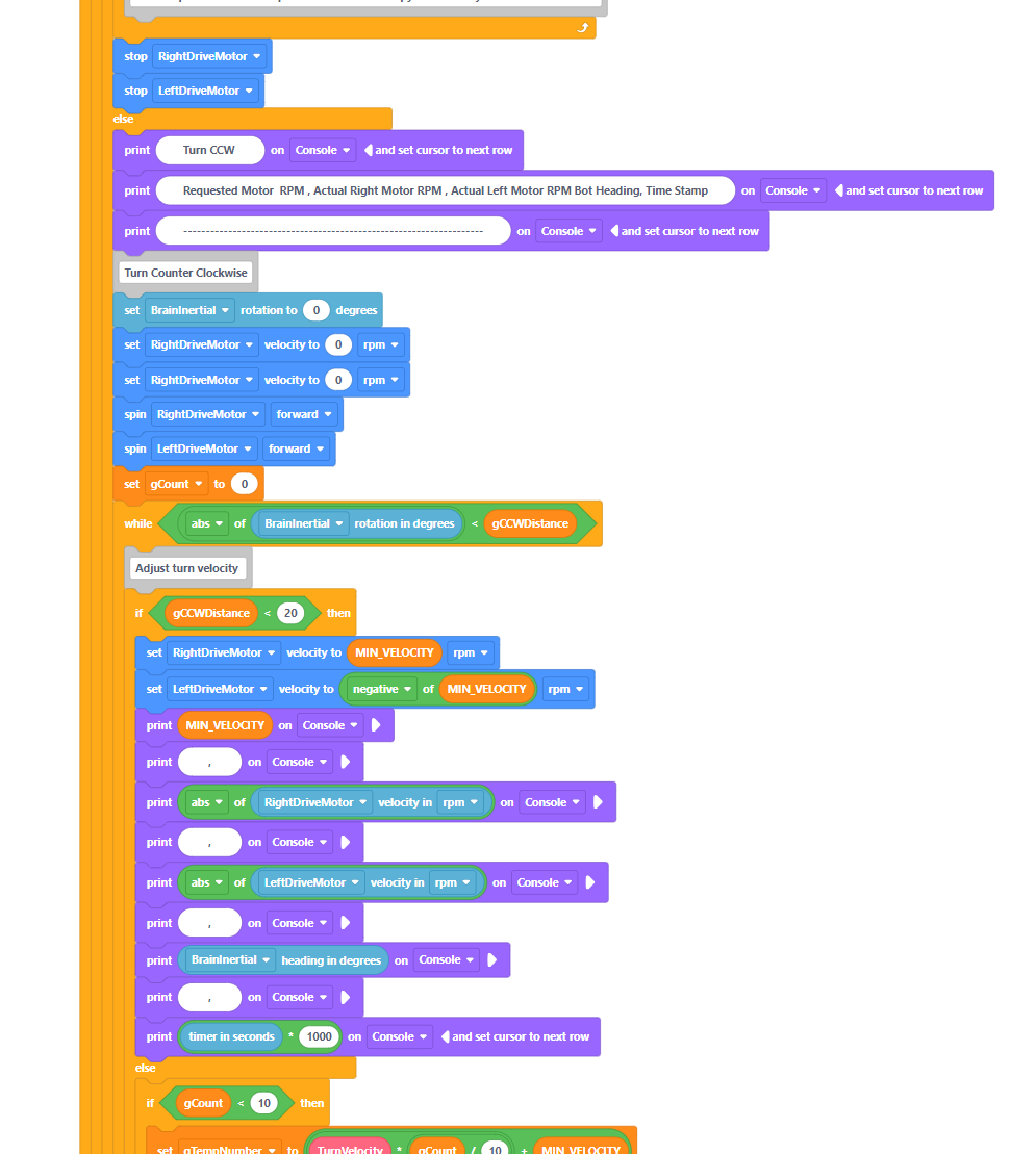
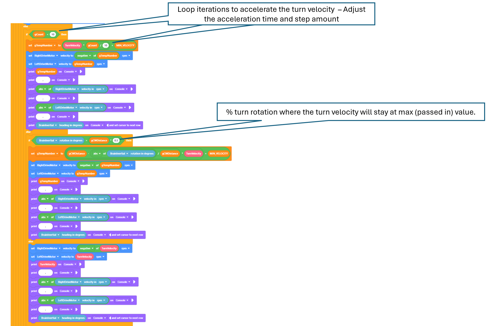
Add the motor velocity adjustment code at the beginning of the while loop as shown.
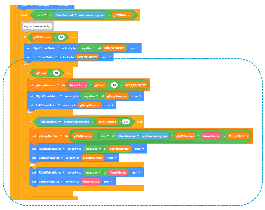
Code Explanation
This code will do the following:
- If the distance to travel is 20 or greater, check how many times the loop has been iterated. If less than 10 (second tunning number), calculate the motor velocity as a multiple of the number of iterations using the equation below.
Step Velocity = (Turn Velocity * (loop iteration count / 10)) + MIN_VELOCITY
This will allow the motors to slowly ramp up speed from 0 to TurnVelocity over 10 steps.
- The else portion of the block waits for the bot rotation to be past 60% (third tuning number) of the desired turn before slowing the bot turn velocity down to prevent overshooting the desired heading.
The equation used to slow the turn down is derived from the PID equation where the integral and derivative coefficients are zero.
Corrected Velocity = (abs(Desired Rotation – Current Rotation) / Desired Rotation) * Turn Velocity
To put it simply the corrected turn velocity is a portion of the passed in Turn Velocity. Thus the “P” in PID.
- The last two blocks just maintain the passed in Max. Turn Velocity until the slowdown is needed.
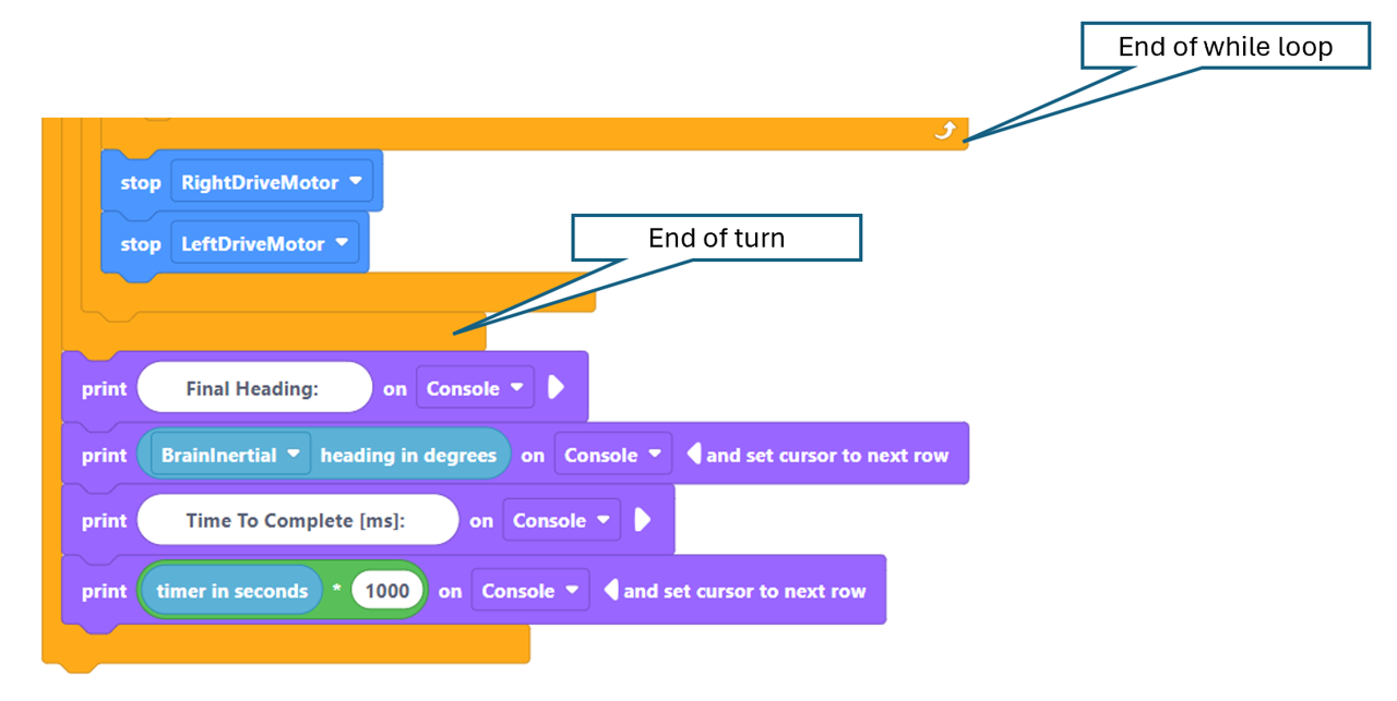
Add the indicated code to print out the motor performance numbers.
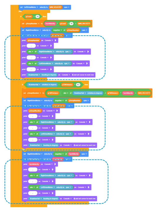
Add these blocks after the loop ends and after the turn is finished,
respectively.
The code for the CCW turn is the same as CW except here the left motor is set to a negative velocity. To complete the CCW turn just copy the CW turn code insert the copy into the else block as shown below.
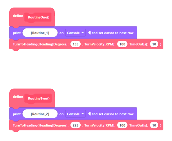
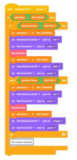
Add code blocks to routines one and two which will require the bot to turn CW and CCW as shown.
Add the event handler for SelectStopTouchLED as show below.
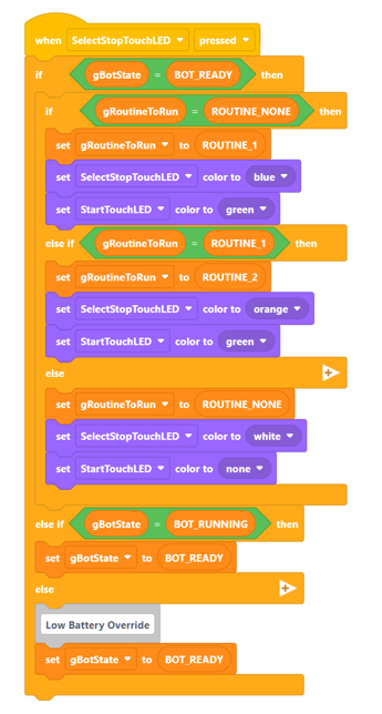
Code Explanation
Provided in earlier post
Using 2 TouchLEDs to select an autonomous routine, start the routine, and stop the routine mid-way. - VEX IQ General Discussion - VEX Forum
Add the event handler for StartTouchLED as show below.
Code Explanation
Provided in earlier post
Using 2 TouchLEDs to select an autonomous routine, start the routine, and stop the routine mid-way. - VEX IQ General Discussion - VEX Forum
The code should now be complete. Here is download link for the competed code.
CustomDriveV1.0.iqblocks (146.0 KB)
Now we need to test this code by adjusting the defined tunning numbers (see below).
Normally I would place these tunning numbers in constants (like MIN_VELOCITY), and we would just adjust the values in a header file. However, we will adjust the values directly in the code to help you learn where and how these values effect the code.
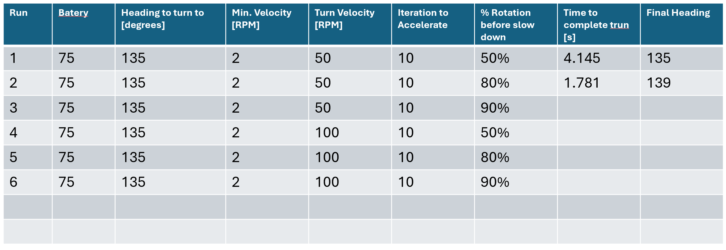
Build a table like shown below. Set the tunning numbers as indicated in the table and record your test results.
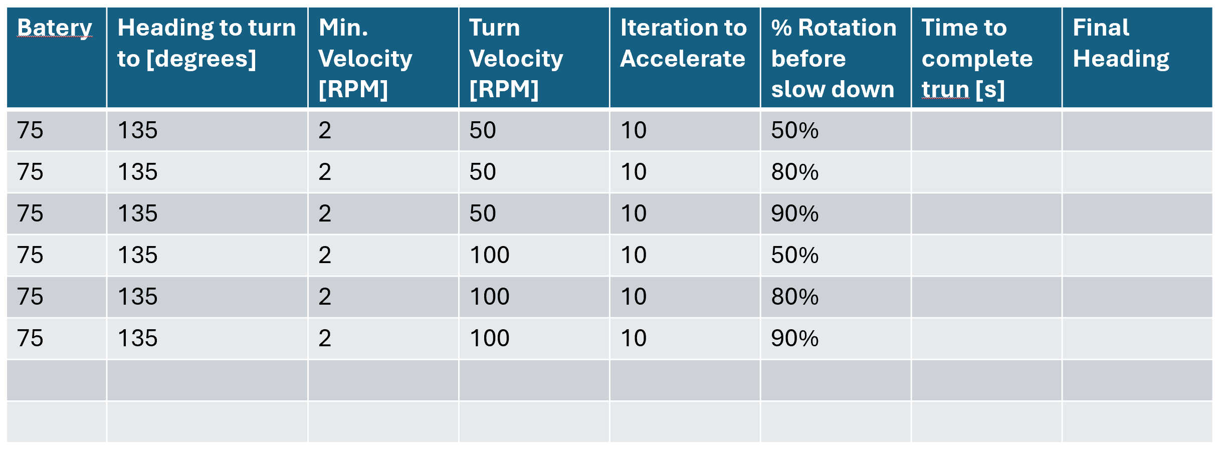
Battery is the current battery charge. When I did this test my battery was at 75%.
The Iteration to Accelerate is defined in the block code (see above) and the % Rotation before slow-down is likewise listed above.
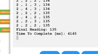
After running a test where the bot is synced with a controller attached to the computer you should be able to see something like the image below in the console window on the computer.
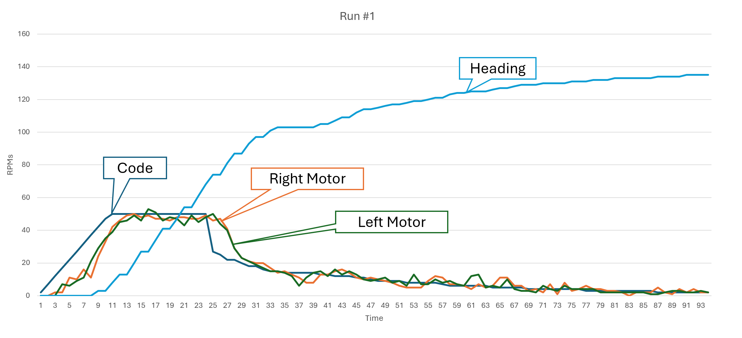
You can take the text from the console windows and using a tool like Excel produce a performance curve graph like the one below.
Reviewing this graph gives you a tremendous amount of information. For example, you can see that up swing and down swing of the two motors is almost identical. That the phase shift is greater on the downside than the upside (Why is that?). Most importantly you can see that the system spent nearly two-thirds of the operation time completing less than 10% of the turn. You will need adjust the numbers to get a better-looking curve. I will leave that to you.
Writing advanced robotic code in Block code is possible. However, the limitations Block code has (see below) will make what is already a challenging task more difficult. I would encourage any VEX IQ team exploring code topics like the ones presented in this post to carefully evaluate the level of effort required to code in Block over the effort to learn C++ or Python.
Limitations of Block code
- All variables are global in scope.
- No functions (no return values) only methods.
- No ability to create a type like an enumeration, a structure, or a class.
- Bugs in the code generator. Sometimes, the code generator fails to produce the underlying code correctly leading to compile time or even run time errors which are difficult to understand/fix.
- Forced to use Python as the underlying language. Python is a scripting language more commonly used in big data projects. It compiles to an intermediate language which must be JITed to native on the device at run time. All of this consumes the limited resources a robot has which will inevitably limit the capabilities of the robot.