So I thought with the popularity of X-Drives this season. (And it being my favorite drive ) I’d release this fairly simple Desmos graph that calculates the exact percentage to spin each wheel at in order to move in a certain direction. (Measured in radians)
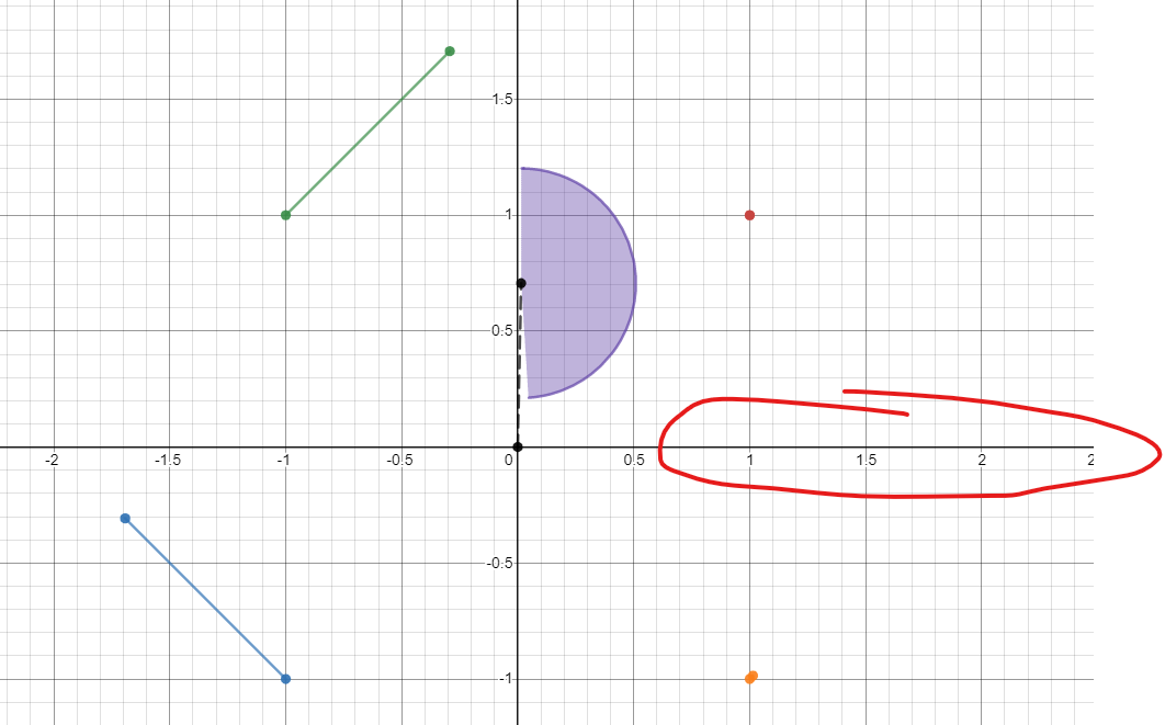
Each colored line shows which direction and how fast each wheel should spin to move in exactly the desired direction. The black dotted line shows the direction and how fast you would move. (Motor speeds are scaled for maximum speed) Notice that you move faster when traveling closer to straight forward and backward than when you move diagonally. I also added a feature to prioritize rotation over movement. The purple arc indicates how much it will turn.
In the variables folder, adjust:
T to change the target movement direction.
R change rotation amount- 1 to only turn right and -1 to only turn left. Anywhere in between to have a balance between the two. (For instance, 0.5 would evenly distribute motor power for moving and turning)
S to change the speed- all motor speeds are automatically scaled so that the fastest one is equal to S. In actual robot code, this is what you would adjust to slow it down for something like a PID loop.
Please feel free to use these equations in your code, but don’t just copy them down, try to understand how it works.
One thing I should add: This was mostly intended for autonomous purposes. I believe this along with odometry could make a killer autonomous. It’s pretty easy to make a joystick controlled drive without all the fancy trigonometry.
Update: I noticed a problem with the visuals. The center line was not calculating its length correctly. here’s the new link. (Desmos creates a new url every time you save your project.)
Ok, I absolutely promise that this might be the last update. I realized that the calculations for slight turns, while looking accurate, were completely wrong. here’s the new link again. Sorry for spamming my own thread.
This is pretty neat. I’m curious though, where were the calculations derived from? I would imagine you could also combine this with a turn PID because the chassis has two degrees of freedom. So, theoretically, you could also change the orientation of the chassis while it’s moving in a given direction, correct? (via combining different PID controllers)
Edit: I’m a bit confused overall about what the graph represents. More specifically, the “R” term. When the robot is moving in a given direction while turning, the wheel velocities change over time correct? Does this means the displayed wheel velocities for the given “R” variable aren’t constant? What happens when the robot arrives at the target orientation? Shouldn’t the wheel velocities change in response to that.
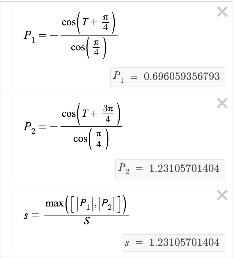
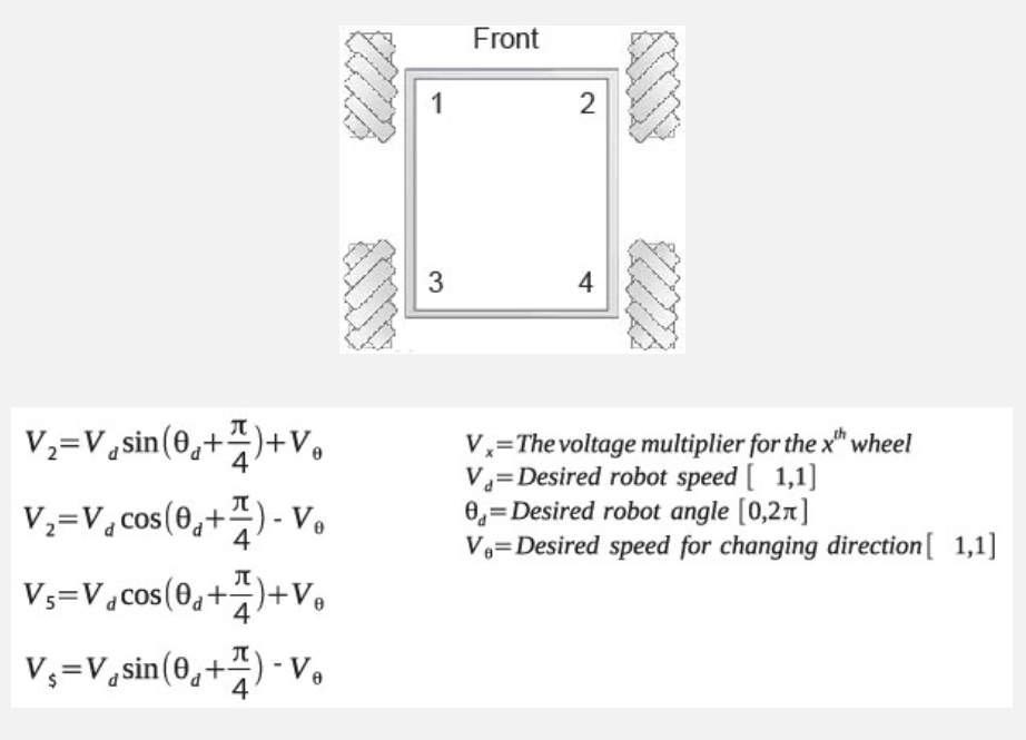
The calculations were basically derived from the fact that the movement along one diagonal was completely dependent on the movement of two opposite wheels, and independent of the other two, and vice-versa for the other diagonal axis. Because of this, Finding the motor value for just moving with no turns is simply finding the x-value of a diagonal (or a point on a circle) but rotated 45 degrees one way or the other. (since it’s in radians, that’s why you see the “+pi/4” or “3pi/4”) in the cosine functions defining P1 and P2. Then to turn, I simply use linear interpolation to choose a value somewhere in between the initial value and 100% in the direction of the turn.
Sorry for the wall of text, I tried to boil it down a bit. =)
Ok, I’m just now seeing your edit, so I’ll explain the ‘R’ term a bit more. Basically, it decides how much to prioritize turning over moving, and its sign determines the turn direction. So if it was R=0, it completely ignores it and just moves. If R = 1 or -1, it completely ignores the moving calculations and just turns. For something like 0.25, 3/4 of the value would be determined by moving, and 1/4 by turning. Does that make any sense?
To drive and turn at the same time, you’d have to figure out both the distance to your target position and the distance (circumference of turn) to your target direction, and then set R to the ratio of the rotation target error to the position error. There are other ways to do it, but this is how you would get it to arrive at the location and face the direction at the same time.
Yep, I’ll do that If I update it again.
Edit: I know I said i’ll edit the original post, but it wouldn’t make much sense for the versions to be out of order, so I’ll put it here. I noticed that S was only scaling the movement, not the turning, so yeah. Fixed.
Edit 2: Eliminated unnecessary variables. I see your questions @mvas, but I’m headed to bed. I’ll try to answer to the best of my ability in the morning.
Updated link:
That makes a lot of sense with the visuals. So the further off from 45 degrees you want the robot to travel, the more power the opposite wheels need to input.
Ahhh that makes a whole lot more sense. I’d imagine this would be somewhat inefficient for longer distances because the total speed of the drive itself depends on the amount of rotating you want to do. So the more you want to turn, the slower the linear speed to the desired point correct?
Even more questions
I have a few general questions as well.
I’m a bit confused here. I understand the basic premise of an interpolation (it essentially fills in the gaps between known data points). How does this relate to turning though?
Another question: So of course you need PID to reach desired wheel velocities to move in a given direction. But, is there a way to implement PID on the global position vector (for lack of a better word)? What I mean by this is is the center point of the robot (as described by the terminology used in the odometry document by the Pilons. It’s not necessarily related to this, but it can be). Meaning, can you scale down the values of each wheel velocity proportionally as the center point of the robot approaches the target point in a given direction? I read somewhere that generally speaking you shouldn’t combine PIDs anymore than the amount of degrees of freedom the robot has. By that metric, what I explained above seems implausible.
Also, what do the values of this whole thing actually represent? The formulas output some number, but how would that relate to my specific robot (should I chose to make one). With PID, you can tune constants to suit your specific needs. Are there any specific units being used for this? These are just general formulas I’d imagine in the same way PID can be a general formula. But, this seems to be like a feedforward algorithm as opposed to a feedback-based algorithm so the units are actually necessary for calculations in this instance, correct?
Edit: I didn’t mean to reply to Ethan, this was just general questions for this thread @Joey_24K. The forums won’t let me change this for some reason.
Ok, here we go. BTW, never mind what I said about being done for tonight. I have a terrible sleep schedule. I’ll try to answer your questions in order.
That is correct, however the example I gave is not the only way to use it. A faster movement could be to tell it to face towards the target (for optimized speed ofc) and drive towards it simultaneously, until it got close enough, at which point it would drive towards it and face the target direction simultaneously.
Linear interpolation can be thought of as a function with three parameters: v1, v2, and L.
Imagine that on the number line, you have a line segment going from v1 to v2. If you start at v1, and move along that line for a distance of L times the length of the line segment. (Where L is a value from 0 to 1) then you get the linear interpolation result from v1 to v2, with a factor of L. For instance, a value of 0.5 for L would simply take the average of v1 and v2. L=0 returns v1, L=1 returns v2, etc.
Before you go on, here’s a Desmos program I wrote up to illustrate it.
So what does this have to do with turning? Well, the ‘R’ (or at least the absolute value of it.) variable is acting as the linear interpolation factor just like ‘L’ was earlier. The speed the motor would move at to just turn is in place of V1, and V2 is replaced with either 1, for turning right, or -1, for turning left. Keep in mind that this is calculated separately for each motor. Here’s a table to make it more clear:
\
R value
resulting motor speed
0
ignores turning speed, just moves
0.25
mostly moves, but adjusts speed by 1/4 to turn
0.5
even balance between moving and turning
0.75
Mostly turns, but adjusts speed by 1/4 to move
1
only turns, ignores moving speed
I actually made this with Odometry in mind. The idea is that you could have a thread/task running this x-drive control code, with, T, R, and S being global variables. You would have to do the math to convert the global target into a local/relative target, but it’s doable. For your question of PID, you could adjust the S value to get smaller as you get closer to your target.
I can see where you’re getting confused here. You are correct that it is essentially just an algorithm that takes in 3 numbers and spits out 4 (1 per wheel) As far as units go, it uses radians for rotation, and that’s pretty much it. No distance units are required, as those calculations would be performed by your odometry or whatever system you choose to use. You tell it, in any given instant, where you want to go and it’ll tell you how to start getting there. However, after a handful of milliseconds, your robot will (hopefully ) have moved, and you’ll need to call the function again to see where to go. Any continuous control from one moment to the next is not what this was built for.
It outputs -1 to 1 for each motor, which you would then map to the minimum and maximum values for your motors.
Ok, I think I got everything. If you’re still confused lmk, I’m happy to help out. Besides, this is pretty good practice for me when I go to write it in my engineering notebook or explain it to the judges. Or my team mates. Or my coach. Or a job interviewer in the future.
More questions condensed to preserve the size of this thread
Where do the -1 and 1 values come from? I’m trying to wrap my head around why there are no units involved here despite the speed of the motor being involved in the calculation. Speed is dependent on units. Are these values arbitrary and 1 is used for convenience? I think I’m just more so confused about the interpolation in general because of my limited understanding of interpolating.
Also, the purpose of the interpolation (in this case) is to find a balance for the motors to move at between turning speed and linear speed. This is because the robot physically can’t move straight and turn instantaneously at the same time. Otherwise, you’d just use a point turn and then drive forward, correct?. It sort of averages it out I guess (biased towards whatever R is).
Related to the above questions, what would happen if you don’t use this ideal ratio? Would the chassis reach the ideal orientation before the endpoint and then just travel full speed linearly the rest of the way? Otherwise, it’d never reach the final orientation until the robot is at the target point?
This makes a lot more sense. I think including this little description is the missing “key” (so to speak) for me to understand all of this. All the calculations shown above would be the only thing driving the motors. The PID would only be in control of the global variables. I always wanted to make a pure pursuit program with an X drive, but I never could wrap my head around the math needed for an X-drive to follow a curved path. This seems like a good way to go about that.
After having typed all this out, I think I have answered some of my own questions, but I’ll leave my questions there in case anyone else has the same questions. Essentially, the units are all arbitrary, and the values output by the calculations are just constants of proportionality based on the max and min values of whatever units you’re using. What I mean is that the motor outputs from the calculations don’t mean anything in isolation, but relative to the units you want to use, they relate proportionally to the max and min of those units (poorly worded I know).
Not really related, but is there any external resource you used or would recommend for more of the theory behind the math (with visuals and such)? This is a really interesting topic
Edit: Could you also define what the variables are/mean in this picture?
I’ll keep this condensed into different dropdowns for different questions.
units
This is correct. There are no real units like voltage or RPM, the range of -1 to 1 was used because you could just multiply the value by the max rpm, percentage voltage, or whatever you feel like using. You may have missed what I said in my last post, which I do not blame you for as it was rather long.
interpolation
This is correct. Instead of facing towards your target and then moving, you start moving towards it and rotating to your target rotation at the same time, similar to moves showcased here: (although with an x-drive and not mecanums ofc) https://www.youtube.com/watch?v=S9eCk-3m7do&feature=youtu.be&t=31
turning ratios
There are plenty of ways to go about this. You could face the target point until close enough and then face your target rotation. This “golden ratio” so to speak ratio would look nice, but it it is not necessarily the fastest. (What if it is facing diagonally relative to the point and ends up driving there with just two motors?)
pid
Glad you got it! Probably should have made the importance of Smore clear, in hindsight. Even odometry and all this fancy directional trig will be useless without well-tuned PID. (At least for precise movements.)
P1, P2 , and s
P1 and P2 are the values calculated for just movement. P1 is for front right and back left wheels, P2 is for the front left and back right wheels. These serve as the “V1” values when interpolating from movement to rotation. s is set to the larger of the two values P1 and P2 so that both can be divided by s later. This ensures that the largest P value is equal to 1 (or to the global var S, since s gets divided by S)
I haven’t looked too much into the desmos math, but I feel like the equations could be slightly simplified (edit: looks like you mostly did this in your recent versions).
Here is another good resource that derives the equations:
I’ll take a closer look at your implementation tomorrow, but just wanted to say I love your approach for visualizing this problem, great job!
Edit:
I played around with it and simplified the math a bit further. Something weird is going on to cause the need for the cos negation but I have to go to bed
That’s cool, the math is almost exactly the same even though it’s mecanums. One difference is that mine only calls the trig functions once each, while the paper has it done for each wheel. Granted, their adjustment for simultaneous rotation is much simpler, but only because It does not automatically scale the values, which would make it much more difficult to program for a practical purpose.
Yeah, I don’t know why i didn’t think of those simplifications.
Edit: I added in @theol0403’s simplifications and also fixed a visual glitch where the black line was too long. Here’s the current version.
The center of rotation would just be the origin of the graph, as it shows the speed of the robot at any given instant, not a distance of movement. The graph only represents an infinitely small slice of time, and the center of rotation would move along with the robot, at the center of all the wheels.
You don’t need to know the distance to find the center of rotation, right?. In this example wouldn’t the center of rotation be somewhere in the red area?
Ok, I see what you mean, where in space the bot is staying an equal distance from. It may be theoretically possible, but there’s no reason for it. I assume this would be for curved paths, but if you want to get somewhere, just drive straight there, otherwise what’s the point of having an x-drive? If you wanted this for position tracking, you’d be better off with three free-spinning tracking wheels and the standard accompanying odometry.