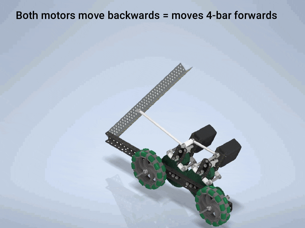
After about a week of work, I have finished modeling/animating a differential drive concept that could be used to power a tilter. This could also be converted to power a DR4B quite easily. I worked on this with some help from my fellow SCA member @ThirdDegree. It uses a differential to share motor power between the chassis and the tilter. When both motors move the same way, the fact that gears move in opposite directions force the mini 4-bar to move forwards, and the opposite when they are reversed. When the motors move in opposite directions, the gear ratios force the 4-bar to stay stationary, as the motors are trying to pull it both ways, but at the same time rotate the gears, spinning the wheels.
Here it is in GIF format
Here is a higher quality version hosted on Imgur:
and as always, the link to the video on my Youtube page:
Feel free to ask any questions about how it works.
Thats kinda cool. I really like how it takes advantage of an unneeded redundancy in the design of goofys and removes it, since you probably shouldn’t drive while stacking. Is there anyway you can share it as a .step so I can take a closer look and recreate it in Solidworks?
Well theoretically if you move the 2 motors at different speeds you might be able to run both simultaneously, but it probably wouldn’t work, and would require very complex code, as well as burning up motors.
Not wanting to tilt and drive at the same time is actually the main flaw of this design. Momentum from the drive transfers into the tilt when you stop or Change direction. You also can’t really have holding power on your tilter, so a macro is a requirement.
You can run both functions at once at the cost of half the motor power, so tilting and driving at 50% speed. As long as you don’t need to tilt to lift, this doesn’t present any major problems.
Let’s say the bot is moving forward at speed x and the tilter is moving at speed y. The motor speeds would simply be y+x and y-x. (I hope I got the signs right, but it’s just a linear combination either way.)
We have a similar concept on our robot. We found that it is necessary to have HS axles on the mechanism or else a lot of the axles start twisting under strain.
@Codec made some good tables to show what I mean but basically let’s say both motors have a range of -100 to 100rpm
Running both at 100 or -100 provides two directions of motion for the first function
Both running opposite (100,-100) or (-100,100) provides two directions of motion for the second function.
If you want to run both functions at once, there needs to be a difference in the motor powers, but you also need to dictate direction. Therefore the biggest difference is when the motors run (0,100) or (100,0) or (0,-100) or (-100,0). This is only using 100rpm out of the 200rpm system so your output speeds are cut in half. Also taking into account that you’re splitting the power to be distributed to 2 different outputs, each output can only receive 50rpm, 25% of the output of the 200rpm system.
We had issues when we were testing our stacking macro, but other than that no serious issues. We were always able to get the 2 minutes out of the motors that we needed
Roughly 15 minutes or so. This will vary based on the weight of the robot, and the build quality of the differential. Use as many screw joints as humanly possible.