Creating a Basic Drive
The drive is the most important part of a robot, without a solid foundation to build on, everything else becomes useless. So for a brand new team, creating a drive which is solid is going to be one of the first hurdles needed to have a decent robot. A few years ago I made a few topics about making competitive, high quality drives (which debatably, neither were).
Quality Drive #1
Quality Drive #2
As outdated and lacking as these resources are, I do still think they have good information when it comes to advanced drives. However neither of these resources are particularly useful to a brand new team.
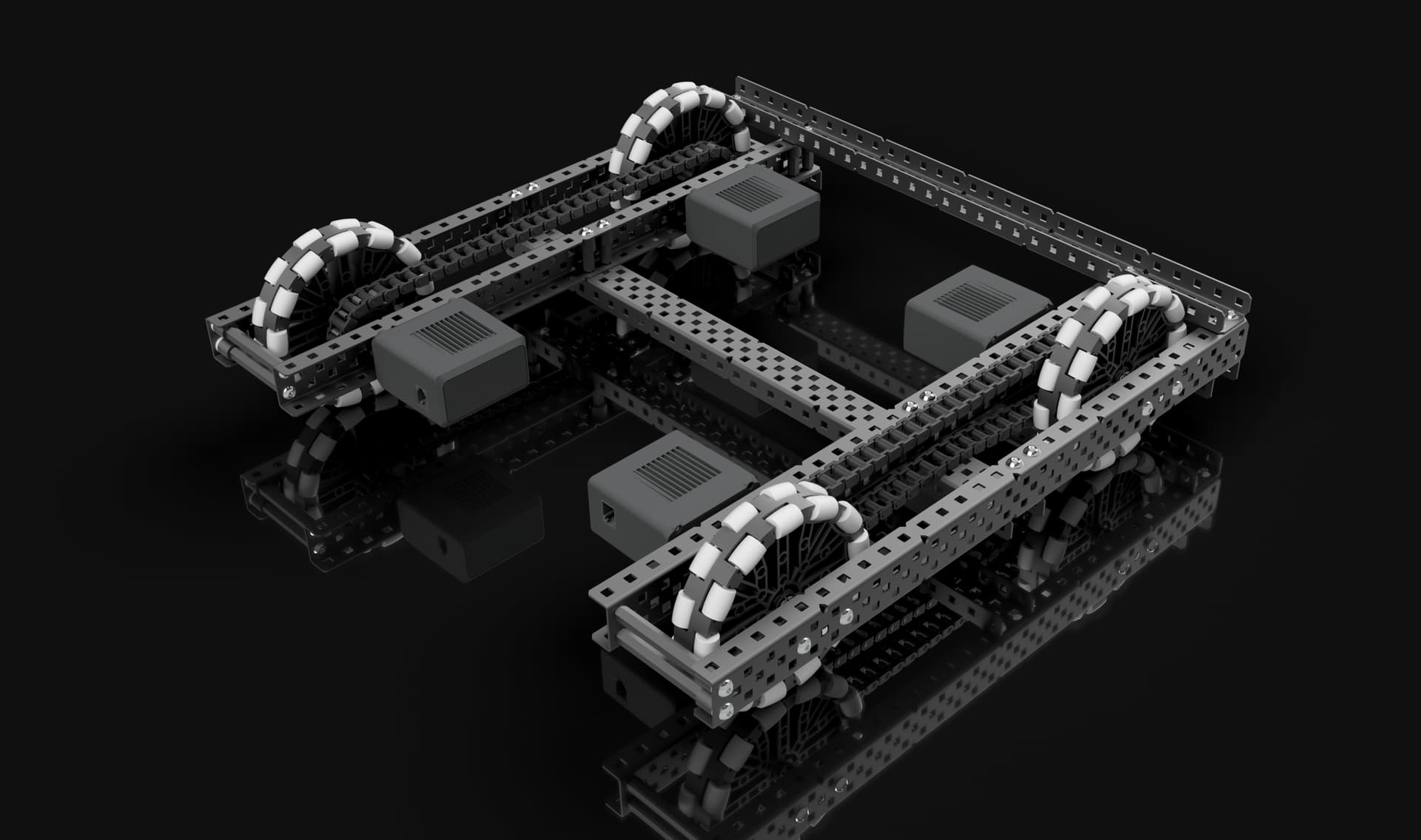
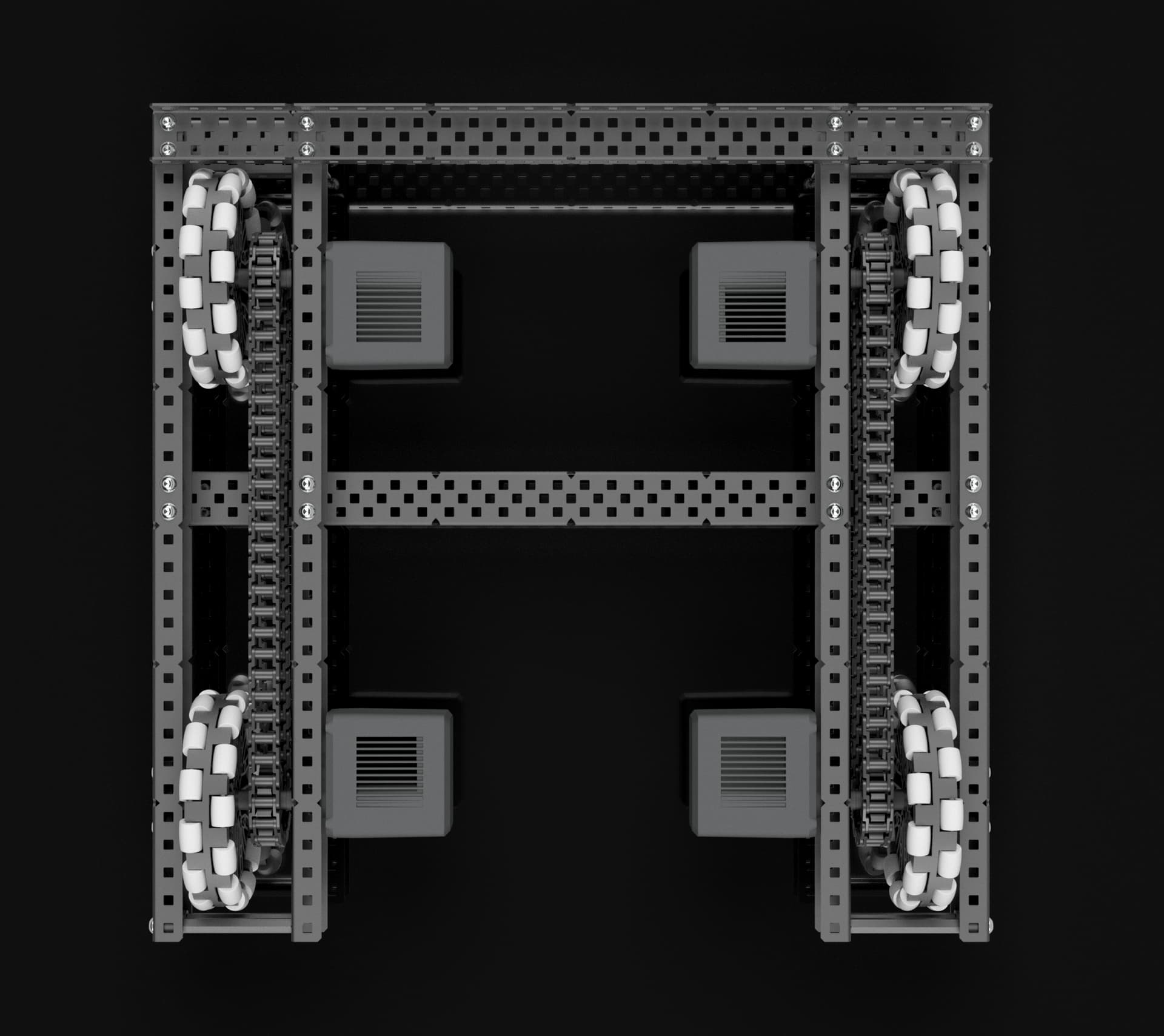
So I’ve put together this resource which breaks down the most basic kind of drive, the 4m direct drive on 4" omni wheels build, or as @Illyana has dubbed it, the “Vex Classic”.
- no screw joints
- no gear ratios
- no advanced part modification
- only 4 motors
- minimal parts
To an experienced team, what I’ve just listed are the reasons this drive is not good. But it is these same things that make this drive simple and easy to make for someone with little to no build knowledge. And while it most definitely is not a good drive, it’s good enough to be the foundation a new team needs to make their first functional robot.
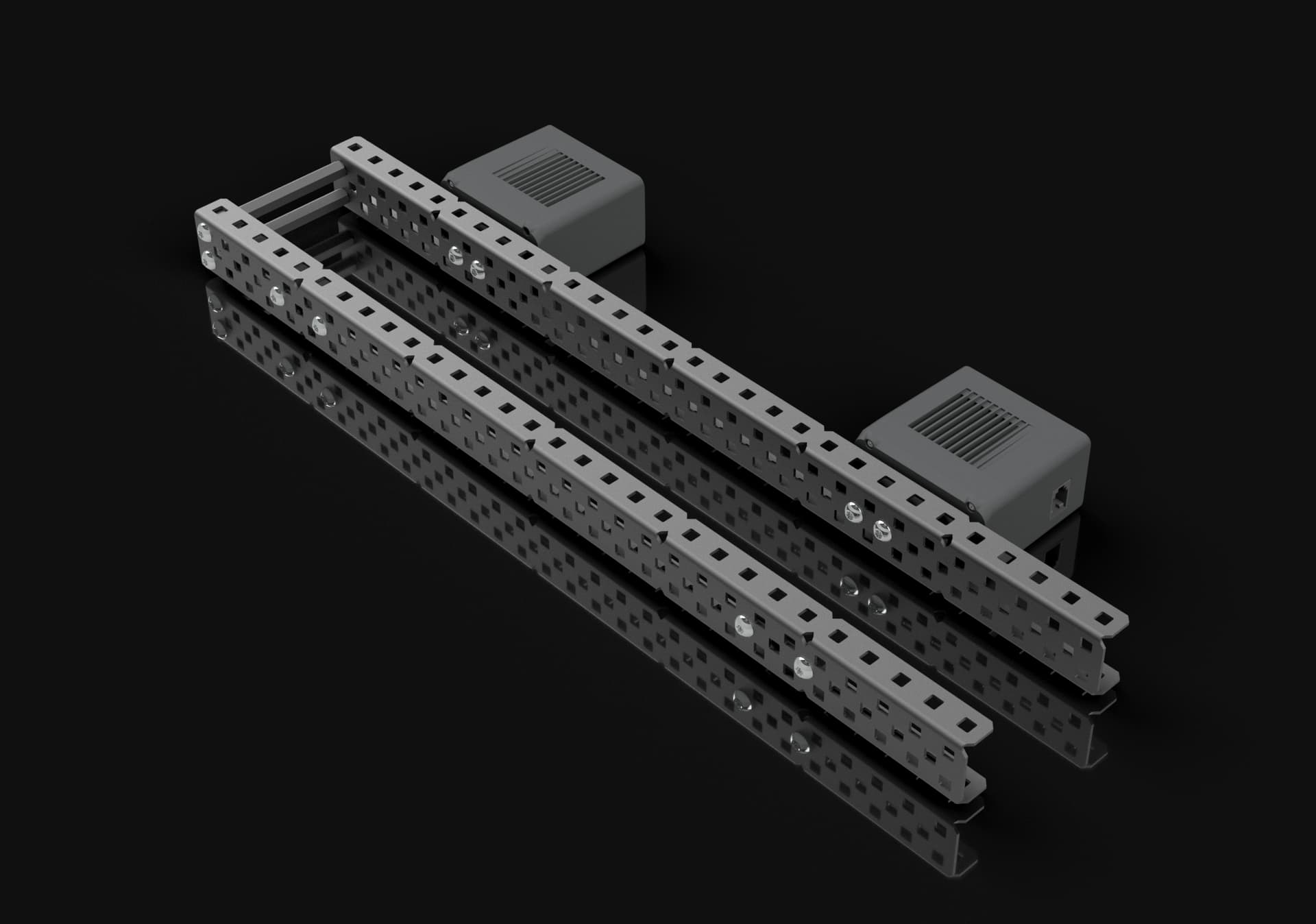
So how exactly does one make and use the Vex Classic?
The picture really isn’t hiding anything, it’s just about as simple as it gets, but I’ll break down each component and point out the important parts.
Structure
Materials
Aluminum c channels are recommended for their lighter weight compared to steel. Steel is stronger, and it will still work, but aluminum is strong enough for just about everything you need it to be.
I used the new anti-static 4" omni wheels for this model, but the old 4" omni wheels would work perfectly fine here as well.
For the screws, I would recommend using a mix of .29" and .5" shoulder screws from robosource. In general I would recommend using star drive screws, and thin nylock nuts, both of which can be purchased very reasonably from robosource.
You most certainly can build this with whatever screws and nuts you have available to you and it will work, but if you are looking to expand your supply of screws and nuts, robosource really is the best place to get a large amount for cheap. The thin nylock nuts are conveniently low profile, and the star screws can come in color-coded heads, if you’re into that sort of thing. But if you are simply trying to build with what you have, don’t feel like these things are necessary, they are not, just nice to have.
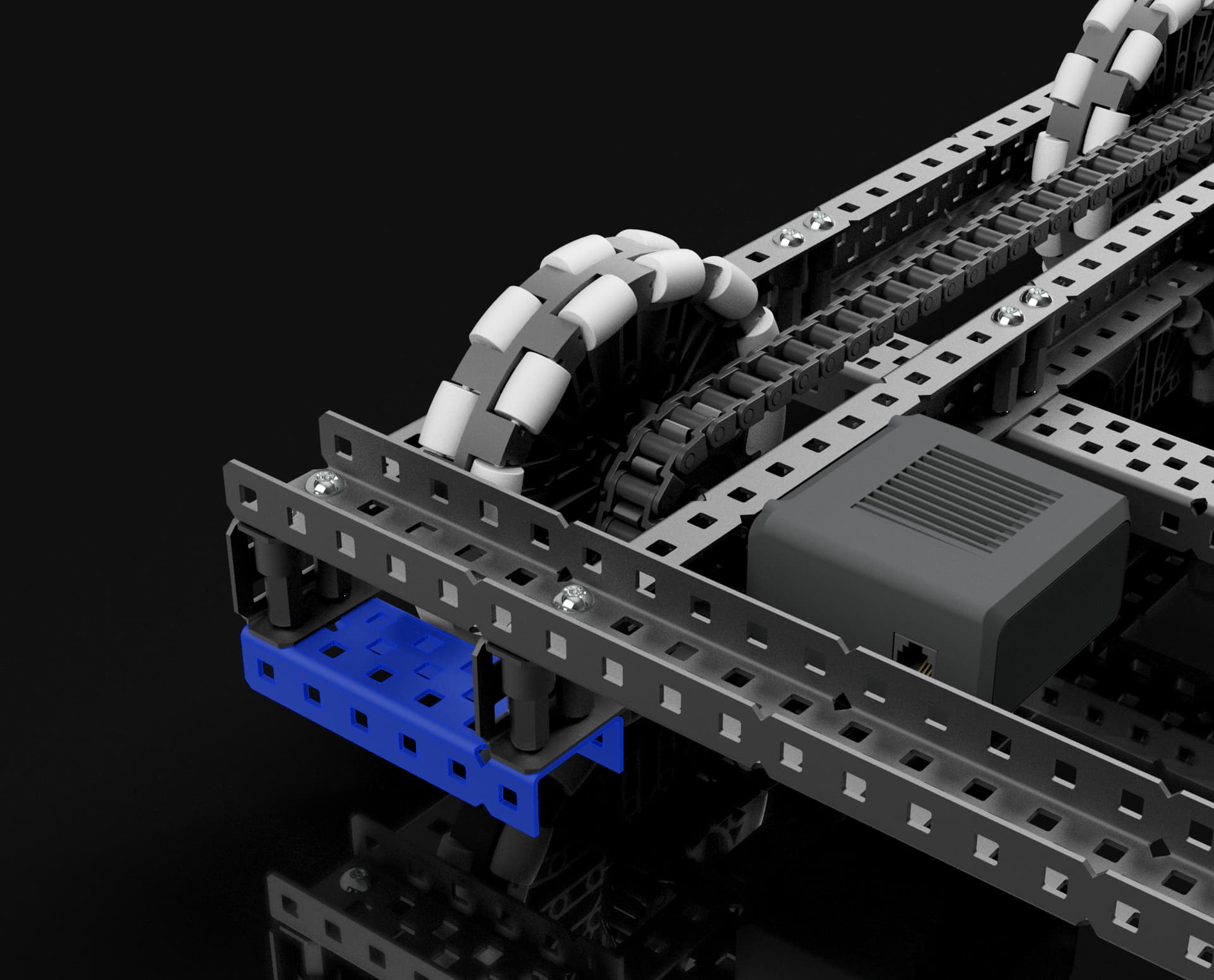
The Pontoons
Pontoons in this context are referring to the assemblies on either side of a drive which house the wheels and gears/sprockets.
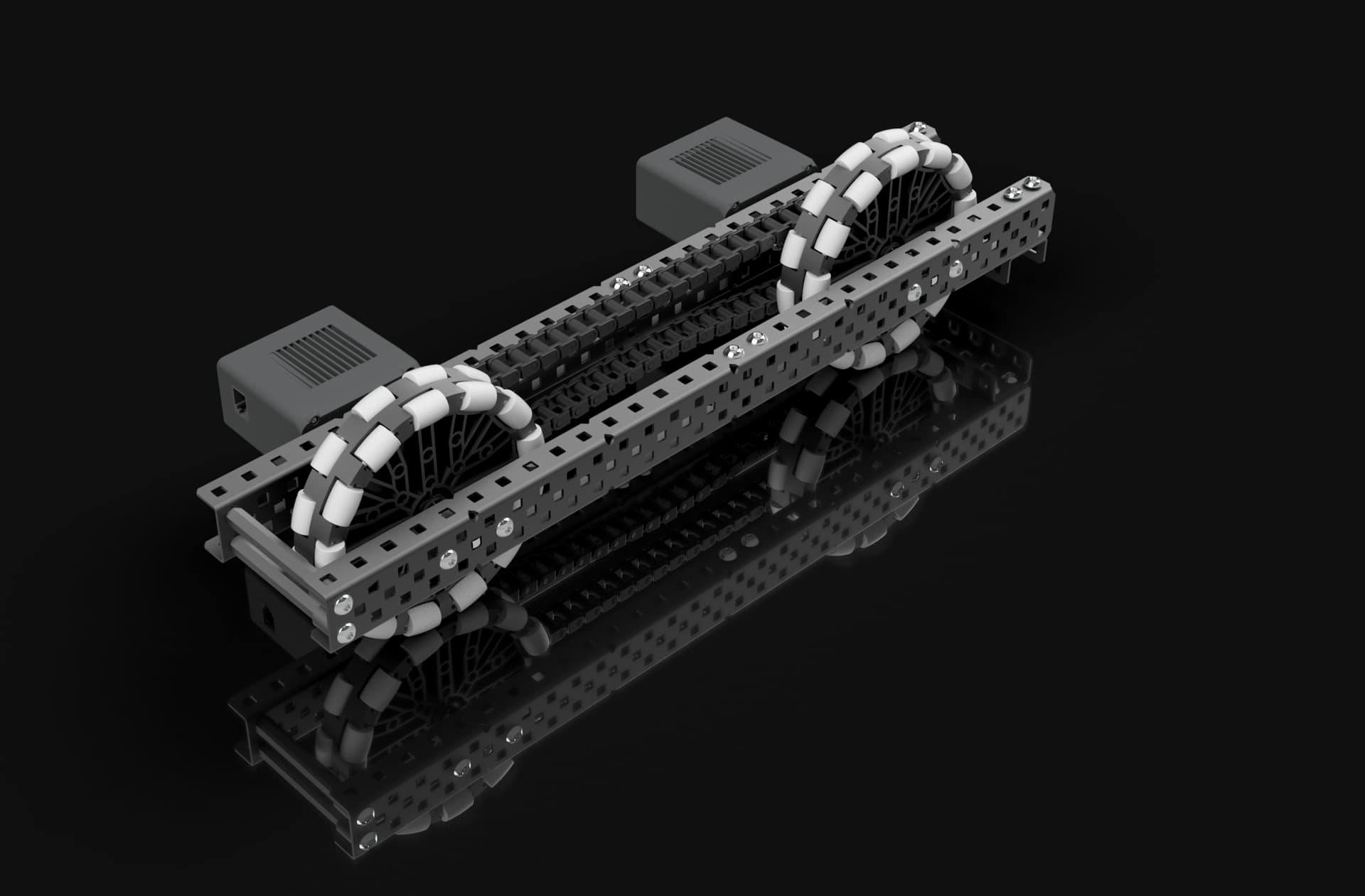
Here is the left pontoon isolated from the rest of the assembly.
The C channels are oriented such that the flanges of both channels faces inwards. A notation for C channel orientations is to type them out with square brackets, in this case it would look like ] ]. Orienting channels ] [ is also generally acceptable, though my personal preference is ] ] for aesthetic reasons. The inner channel should always be flanges inwards though, because it lets you mount your motors more compactly.
The pontoon is capped at both ends by some sort of brace. The main purpose of these caps is to keep the two channels of the pontoon securely mounted to each other with the right distance and position. Without a cap, the ends of the c channels could angle away from each other, which is bad. The cap also protects the wheel from taking any direct impacts. There are a lot of methods you can use to cap drive pontoons, here are the methods used in this drive:
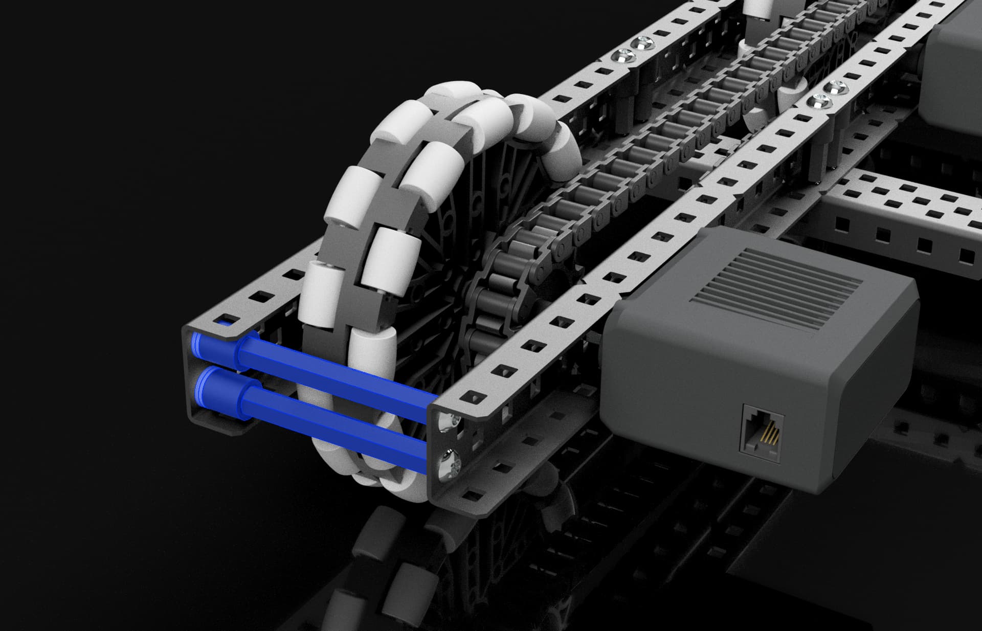
At the front of the Pontoons, these standoffs form the cap. Standoffs are great under compression and especially tension, which makes them a decent pick for capping pontoons, especially on the front of the pontoons where typically you won’t put a full cross brace. Be mindful when using standoffs for this that you don’t want the spacing to be too much or too little, or it will forcibly bend the drive channels in or away from each other, which will ruin their alignment and spacing. Generally, you should need to use some spacers and washers to get the spacing just right. Shoulder screws are also recommended here to ensure the standoffs are centered in the c channel holes.
At the rear of the pontoons, the highlighted 6 hole c channel acts as a cap along with the rear cross brace. The 6 hole c channel is probably the least essential brace on this drive considering the cross brace above it would still be acting as a cap were the 6 hole c channel removed. But without it, the sides of the pontoons might be able to bend inwards at the bottom, which could cause misalignment of holes and friction in the wheels.
One important thing to note is that while standoffs work well for capping pontoons, they should not be relied on exclusively to hold the outer channel to the inner channel. It is important to also use at least a few channels to connect the inner and outer channel, because channels are strong under perpendicular forces while the connection between a standoff and a c channel isn’t. But this can be the job accomplished by bracing, not necessarily pontoon caps.
Cross Braces
Cross braces have the job of connecting the pontoons and supporting the weight of the robot without buckling, all while keeping the drive square and steady.
It’s crucial that you have enough cross braces to firmly connect the pontoons together. If the pontoons are held together well, you can get away with just a single cross brace that goes across the entire drive, with others just going across the inside. This is good because once you start using gears in your drive, you can find yourself with very few convenient places to put braces which span the entire drive. But because this drive uses chain, a cross brace can easily be installed across the entire middle in addition to the back.
One of the major jobs that cross braces do is minimize the potential for torsion between the two drive pontoons. If you grab one pontoon in each hand, and try to twist them against each other, you’ll find that there is some amount of flex. The goal is to minimize this flex as much as you can.
Another important thing cross braces do is keep the pontoons affixed in a way that is level to the ground. Because of the robot’s weight distributed on the wheels, the pontoons will want to buckle inwards. As long as the pontoons themselves are properly rigid, the only ways it can do that are if the cross braces themselves bend in the middle, which can happen if you aren’t careful about how much weight you put on them, or if the flanges of the pontoon channels they are mounted to bend. This is the more likely thing to happen, because a c channel flange has no problem bending under minimal forces. The way you can prevent the flanges from bending at these crucial mounting points is with a build technique called box bolting.
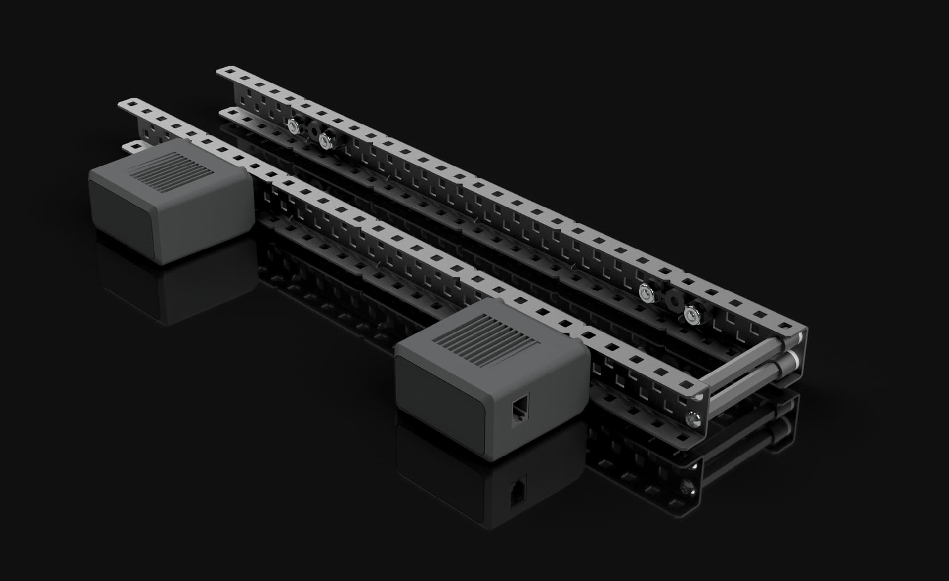
Box bolting is where you fill the gap between a c channel’s flanges with spacers or standoffs, so that it becomes almost impossible for the flanges to bend. Here is what it looks like to use box bolts:
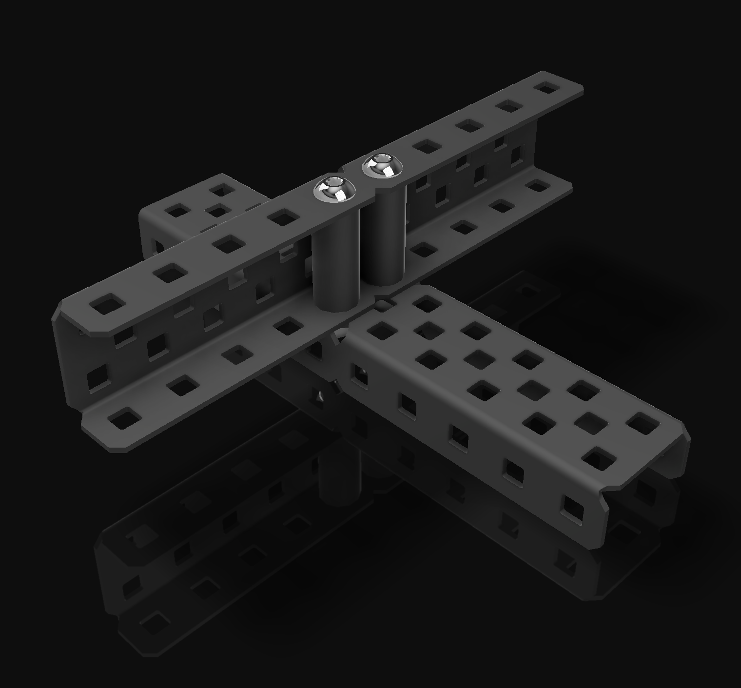
In this example, a .5" spacer and a .375" spacer are stacked and crammed into the c channel, and then a 1.25" long screw is inserted through the whole thing, and a lock nut is used on the underside to secure the whole thing together.

In this example, a .5" standoff is used in place of a .5" spacer, which allows the use of a screw on both ends of the bolt, which is cleaner because now there’s not a nut sticking out on either end.
Box bolting is a great technique that should be used whenever you mount something to the flange of a c channel and there is space to do so.
In this drive, box bolts are used to attach the cross braces, as well as the rear pontoon caps.
this ensures that the flanges of these c channels are almost completely unbendable at the points where they need to be. Sometimes it isn’t possible to box bolt drive braces due to bearings being in the way, but when you can, you definitely should.
One important note when to comes to box bolting, beware of over-tightening the screws. If you tighten them too much, the spacers in the box bolt will become squished and compressed, and the flanges will start to bend inwards. Box bolts should be firmly tightened, but avoid tightening them to the point where the box starts to get crushed.
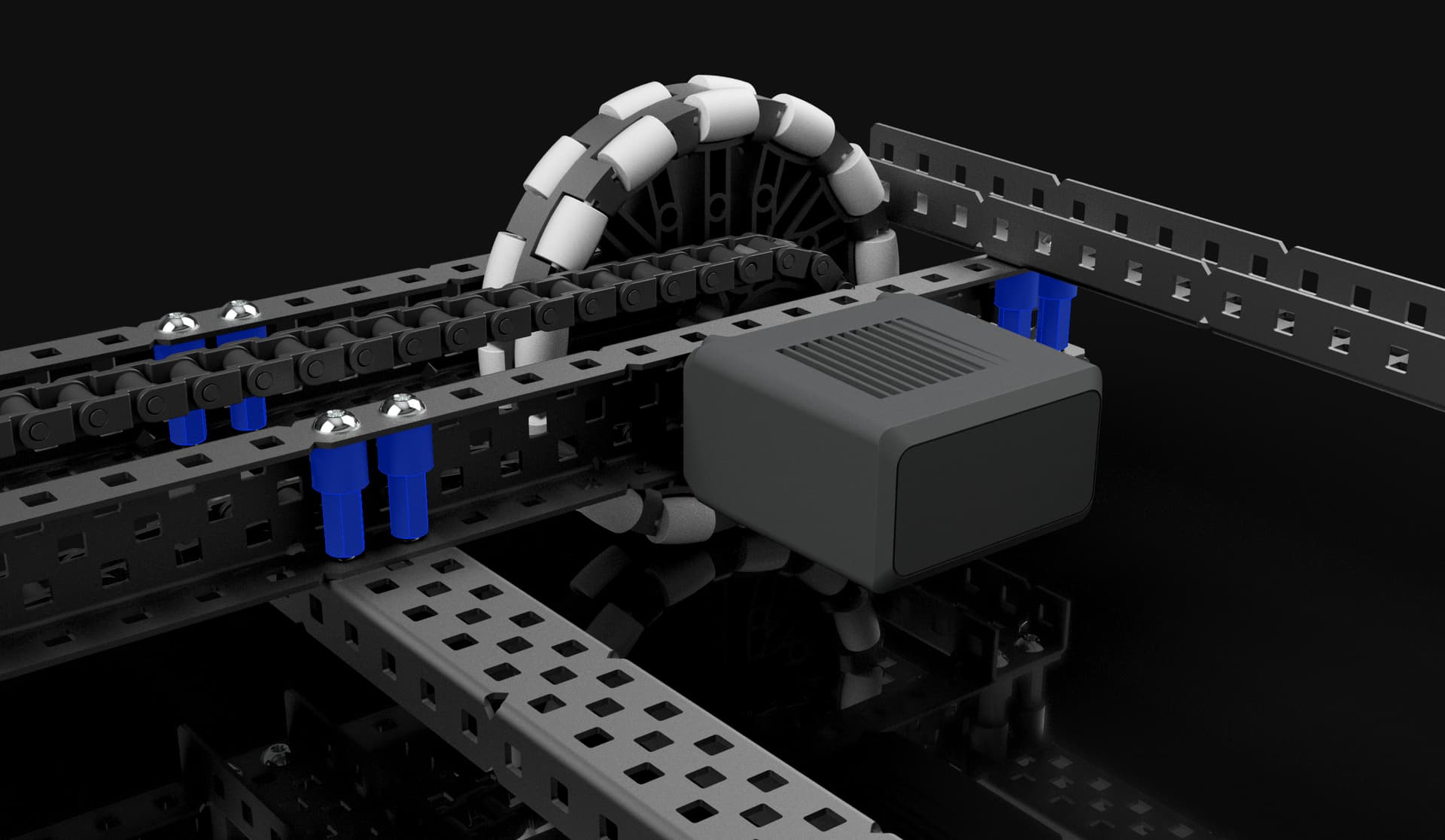
Mounting Towers
one feature that just about every robot needs are vertical towers to mount things off of. But the methods of attaching c channels vertically off of a drive are surprisingly not well documented.
A method I picked up a while back that I found really nice was to use a 1 hole long slice of U channel to form a horizontal flange on the c channel that allows it to be mounted upright on almost any horizontal surface.
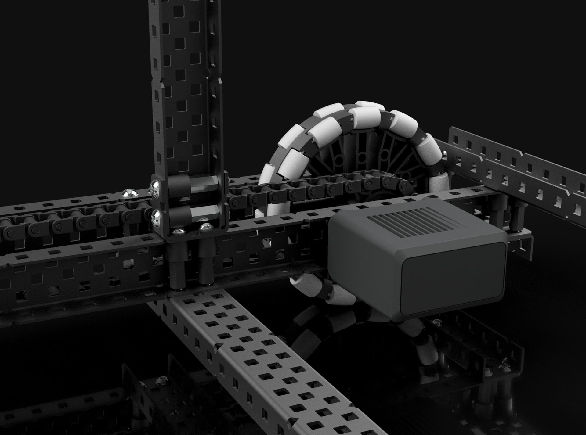
It also makes it easy to mount towers on the same box bolts that attach cross bracing (or the other way around), which increases the strength while saving weight in mounting hardware.
There are of course, other ways to mount towers and it the ideal mounting will change depending on your design.
Motion
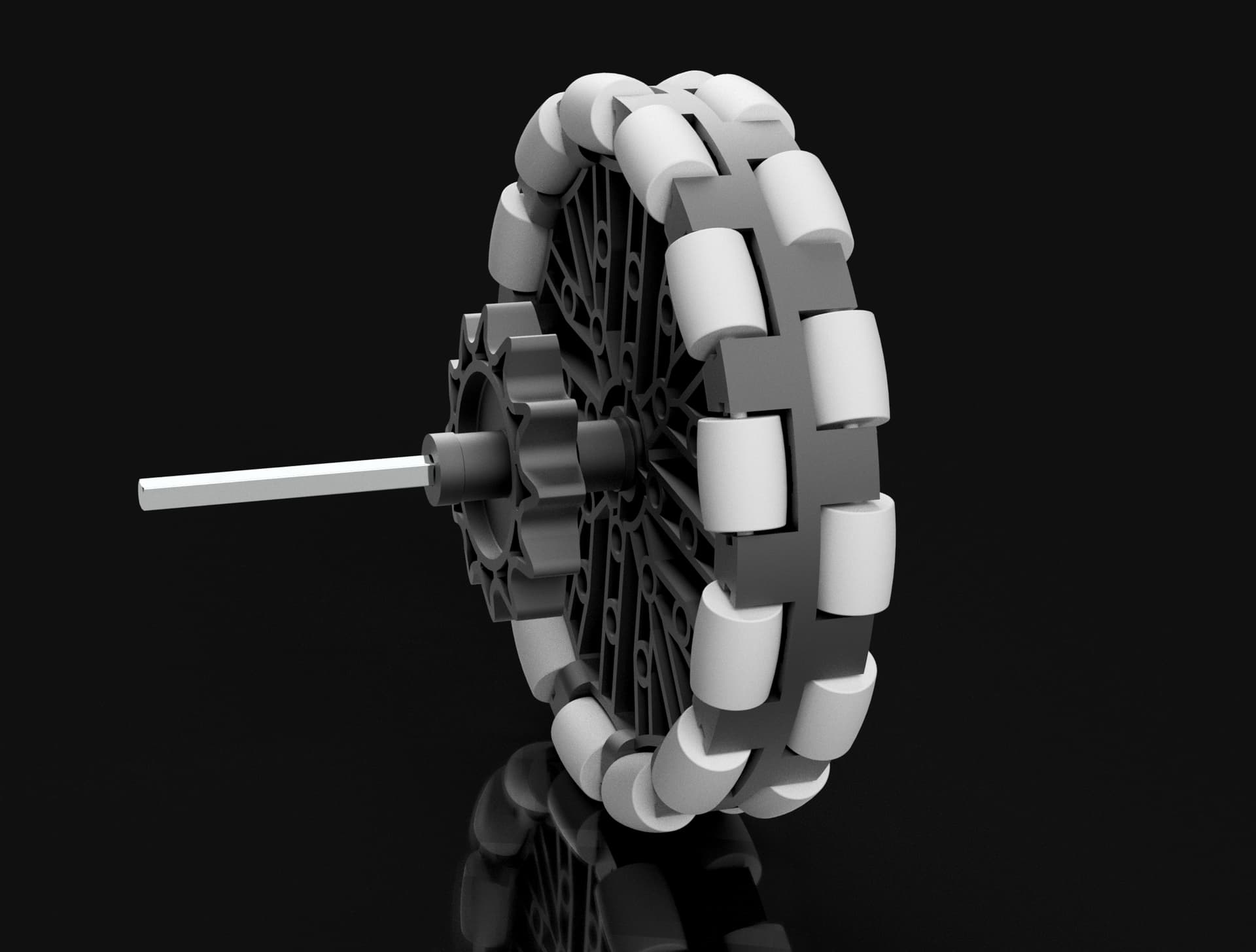
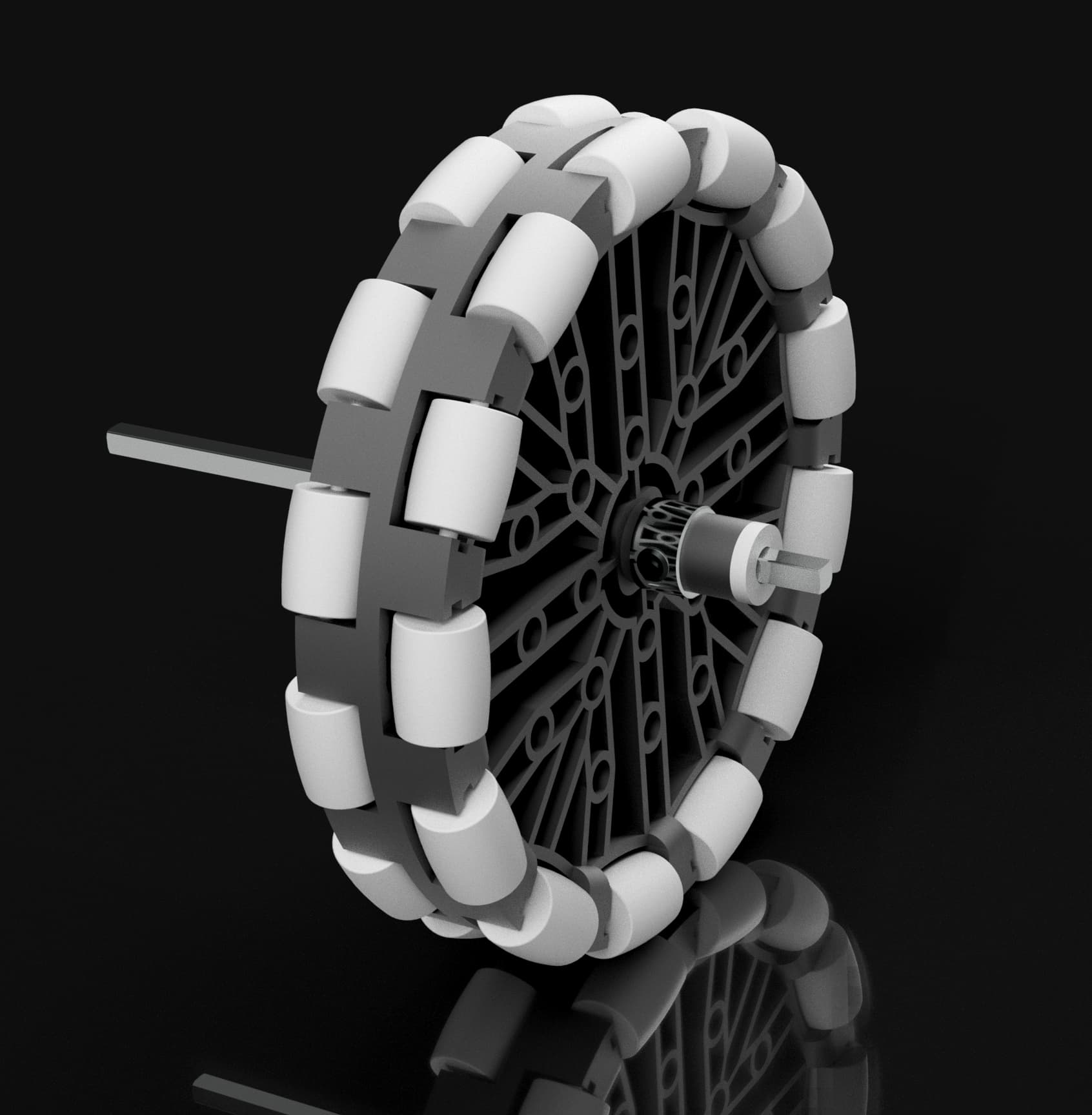
Wheels
This drive uses 4 4" omni wheels running at 200 rpm. The reason 4" wheels are chosen here is because 3.25" and especially 2.75" wheels are very slow at 200 rpm, and only 4" wheels gives a reasonably decent speed at 200 rpm with no gear ratios.
Omni wheels are chosen for their turning ability. If a robot which has 4 traction wheels and attempts to turn, the traction wheels are forced to scrub sideways on the tiles, which is unpleasant to drive and causes inconsistency when trying to turn precisely. Using all omni wheels allows the robot to turn smoothly with no wheel scrubbing, since the rollers allow for the wheels to move sideways freely. The downside of using all omni wheels is that you can be pushed from the side quite easily. Despite this, many top teams still chose to use all omni wheels because they enjoy the smooth driving they provide and a driver skilled enough can make use of the sideways drifting. The alternative is to have a single set of traction wheels, which still allows for turning without scrubbing, but eliminates drifting and resists sideways pushing. You could experiment with using traction wheels on the front or back of this drive, and you’d find that the robot’s center of rotation will shift to be between the traction wheels. This isn’t necessarily a bad thing, but what a lot of teams do as well is add a third set of traction wheels to the center of a drive to keep the center of rotation centered. This type of drive is not that suited to this sort of layout though, and it would take some level of modification to add that.
Power
The way power is handled in this drive is very simple. Each wheel is attached directly to a motor, which is known as direct-drive. In addition to this, the wheels on each side are linked to each other using sprockets and chain. The purpose of linking the wheels in this way is that if one wheel is lifted off the ground or loses traction for any reason, the power from that wheel’s motor is redirected through the chain to the other wheel, meaning that you are still getting both motors worth of power. Another reason for linking the wheels is that it ensures both wheels move in sync and at the same speed. It’s always good practice to link each side of the drive together, even in the most advanced drives.
Chain is generally frowned upon when it comes to drives. The reason for this is that it snaps, and if you build this drive and use it enough, I guarantee it will snap at some point. For most teams, this is an unacceptable risk to take on the most essential system, and I would agree that you shouldn’t use chain on your drive. Except in this case. The reason this is different is that both wheels are connected directly to a motor. So when the chain breaks, both wheels keep moving and the drive can continue to operate almost as normal. You lose the synchrony between wheels and the power transfer if one wheel loses contact, but the drive will keep on moving and it won’t cause you to lose the match. What I mean to say by all this is that chain is acceptable only when it can snap without breaking the drive.
With this chain, it is important to not make it too tight or too loose. You want it to be just tight enough where it can’t skip, but still loose enough that there is some slack. Having the chain pull tightly at the sprockets forces the shafts to press against the bearings and increases friction, and it also increases the chance of the chain snapping. The chain will also drag across the middle cross brace, but that is ok, it doesn’t cause issues to have chain gradually slide over something.
Joints
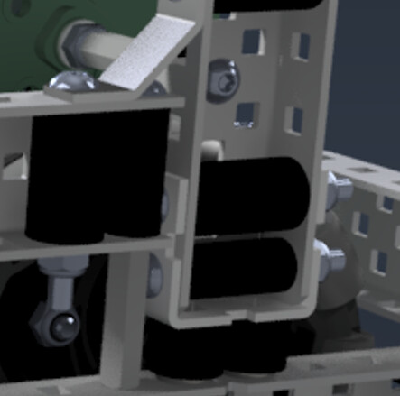
This drive has only 4 joints, one for each wheel. These joints are shaft joints, which is necessary so that the motor can drive the shaft and transfer power to the wheel and sprocket.
The spacing on these joints is pretty forgiving as far as tolerances go, but the important things to consider are that the chain and the wheel need to not scrape against each other or the sides of the pontoons, and that the spacing needs to not be too tight. If spacers are crammed into a joint where they don’t easily fit, they will push up against the sides of the joint and create a lot of friction. A good rule of thumb with joint spacing is that you should leave a gap big enough to stick your fingernail in. You should also avoid any metal-on-metal rubbing, which means that shaft collars shouldn’t be touching any c channels directly. Separate shaft collars from metal with at least a washer.
Another important part of this joint is that both the sprocket and wheel need to be locked to the rotation of the shaft, using square inserts. This way the motor is able to transfer that rotational motion through the shaft into the wheel and sprocket. Try to avoid using old omni wheels or sprockets that have plastic square inserts because those tend to wear out and let the sprocket or wheel wiggle against the shaft. This sort of backlash is referred to as slop, and on a drive you really want to reduce the slop to the amount inherent in the motors.
Another hugely important part of joints is what the joint is spinning on. In many cases, including this one, that thing is a bearing flat. Bearing flats provide a smooth, round hole for the shaft to spin in. Without the bearing, the square shaft will be pressed and ground against the square hole, which will eat away at the metal and create huge amounts of friction. The shaft should never come into contact with the c channels at any point.
In general, a spinning shaft should have two points of contact that it pivots in, ideally on either end of the load. In this drive, 1 of those points of contact is the bearing on the outer channel. However, there aren’t any bearings on the inner channels.
The reason for this is that the motor itself supports that end of the shaft, and will keep it from touching the c channel. Adding another bearing on the motor side will create 3 points of contact, and that is undesirable. The reason for this is that with 2 points of contact, there will always be a straight line you can draw between the points, and so even if one point is not 100% concentric with the other (which will always be the case, vex parts only have such good tolerances), the shaft will still be able to spin freely between the points. But if you add a third contact point, than all 3 points need to be perfectly aligned or else the line that goes through them all will not be perfectly straight. The impact of this can be insignificant if the holes are aligned very well, but it’s significantly harder to do that compared to with 2 contact points. For this reason is it recommended not to use bearings on the motor side of a driven shaft joint.
Programming
This guide isn’t meant to be an introduction to programming with vexcode, so all I’m really going to do is point to some resources that can help you get started.
Configuring the drive
Once you have a working drive, you need to program it so that you can actually drive it around.
If you’re using vexcode v5 (blocks), see this article on configuring a 4 motor drivetrain. If you’re using vexcode v5 pro (text), see this article instead.
Alternatively, you can configure each side of the drive as an independent motor group, which will could give you more control over the behavior of the drive.
Be sure to use the competition template for vexcode blocks or text so that the robot will run autonomous or driver control when it is supposed to during competition.
Creating Driver Controls
Now that you have your drive configured, you can program the manual controls. The easiest way to do this is to configure your controller in the devices menu, and assign the joysticks to your drive directly without any real programming.
Here is an article on how to do it in blocks, and in text.
Alternatively, you can manually write some code in the driver control section of the competition template. This allows you to have more control, and lets you do things like joystick curving, which are not at all necessary but can help a driver get finer control without sacrificing top speed. If you’re interested in programming the drive manually, this is a good video tutorial which is applicable for this drive.
One thing you might hear debated frequently is what control scheme is best for a drive. The 3 main layouts are:
Tank Control, where moving the left stick up and down controls the left side of the drive, and moving the right stick up and down controls the right side of the drive.
Arcade Control, where moving a single stick up and down makes the drive go forwards or backwards, and moving the same stick side to side makes the robot turn left or right.
Split Arcade, which makes one stick control the forwards and backwards movement of the bot while the other stick controls the turning of the robot.
Despite what you might hear, this is 100% up to driver preference and there is no objective reason why any one of these is better than the other. My personal preference was tank control, but all 3 are viable options for your driver. My recommendation is that you experiment with all three for a little bit, find which one you like the most, and stick with it.
Controlling the Drive in Autonomous
Drive control during autonomous is one of the most studied and advanced topics in vrc, with the ceiling being constantly pushed higher and higher. But it’s also very easy to do basic movements during autonomous without any advanced knowledge.
See this topic for some examples of basic motor group and drivetrain commands in vexcode v5 pro. In blocks the commands are pretty self-explanatory, they will do exactly what they say on the blocks.
If you have more advanced programming knowledge and/or are interested in learning about more complex autonomous drive control, this video is a good introduction to pid controllers.
In general though, someone brand new to programming can have do well enough sticking with the basic integrated drivetrain commands.
Troubleshooting
Friction
Friction is the top culprit in most problems you might encounter. There is lightly some friction issue if your drive is doing any of the following:
- motors overheating, slowing, and stalling out
- drive veering to one side
- squeaking or grinding noises
- sluggish acceleration
Unfortunately, friction can also be annoying to pinpoint and eliminate. The best course of action when troubleshooting friction is to first do a visual check to see if the source is obvious. Look to make sure the frame is nice and square and no c channels are bent or angling. Spin the drive and see if you can spot any places that the wheels or chain could be rubbing against something. (the chain will rub gently against the middle cross brace, however this is intended and will not cause any significant friction).
Check to be sure the spacing on the joints isn’t too tight, and that the chain isn’t over-tensioned either.
If not source is immediately obvious, take off the chain, and raise the drive so that the wheels aren’t touching the ground. Spin all 4 motors forwards at full speed, and then suddenly stop. Visually look to see if any wheels stop spinning significantly sooner than other wheels. The wheels that stop first are the ones which have excess friction in their joints. Examine those joints to check that the shaft is straight, and that the bearings are properly seated in the square holes such that the shaft cannot make contact with the metal c channels. Also check the alignment of the motor, if the motor is shifted or mounted with poor alignment, it could be allowing the shaft to grind against the c channel the motor is mounted to.
Motors or Ports Burning Out
unfortunately, it is a known and common issue with the v5 system that ports on motors, and more commonly on the brain, can be fried by static electricity and broken. The usual signature of burnt ports is that the port becomes unresponsive, and will make very short red flashes of light. There is no competition legal way to repair these ports, and the best thing you can do is try to prevent them from happening by using the anti-static field tiles, anti-static spray, and avoid driving in dry conditions if possible.
Drive not moving as expected
if, when you try to move the drive, certain motors are not spinning in the direction you expected them to, it is almost certainly a programming issue. Double check your code and device configurations to make sure the direction of all motors is correct.
I hope this resource is helpful for teams building their first robot. Remember that while this drive is by no means good, it is decent, it is functional, and it will give you a solid foundation to build your first robot off of. Have fun, learn what you can, And in the wise words of @AperatureLabs:
Feel free to ask any questions you may have about this build, and add on if you can think of any other information that would be useful to someone making their first drive.