A topic I created almost a year ago, designing a quality drive, has been a relatively frequently used resource. While I believe it’s still relevant as a resource, I’ve learned much since then and I felt it could use an update. So here we go, designing another quality drive.
Quality Drive Version II:
Design Process
Here I’ll be detailing the process of designing this particular drive, and explain why it is how it is.
Size
I chose to make this particular drive small in profile, measuring 25x25 holes. I chose this size because I wanted a lower profile, more maneuverable drive with plenty of room for intakes and other mechanisms that could need to stick out. At this size, you essentially have 10 holes of space to work with on the front (or back) and 5 holes on each side. For a game like change up or tower takeover, smaller drive sizes were often advantageous, as it allowed robots to have static intakes (that is, intakes that don't require a deploy at the start of the match).I also chose to make the drive small because the shorter a drive is, the fewer gears you need to link the very front and back wheels, which means lower complexity and friction overall.
However, this type of drive could easily be adapted for a larger size. Widening it is trivial, just lengthen the cross braces. Lengthening it is more difficult, you could either add 2 more gears to the front, which adds more friction, or you could do something like what many change up robots did, which is to have a very short drive, and then have some fixed, free-spinning wheels on the front of the drive to prevent tipping. Some examples of this are 2616j and 62a during the change up season.
As far as C channel size goes, I opted for 2 wide c channel this time, as there’s not really any advantage I’d gain by using 3 or 5 wide with this particular design, and compactness was one of my key goals.
Gearing and Wheels
Let me preface this section by saying I have a strict personal policy against using chain for a drive. Many teams have used chain with large amounts of success, but I simply am not willing to risk the function of the most important part of my robot on a loop of plastic snap in place chain. I am willing to accept the extra complexity and friction as a tradeoff for the added reliability and reduced slop. Well worth the trade in my opinion, however you can certainly use chain if you so choose. Just make sure you are aware of the risks.
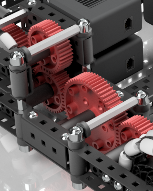
For this drive I’ve chosen to use a 3:5 gear ratio with 600 rpm motors on 3.25" wheels, which is 360rpm.
This is equivalent to 292.5 rpm on 4" wheels, and is roughly 46% faster than the basic 200 rpm direct drive to 4" wheels.
This gives a lot of speed to work with, and you really wouldn’t want to go faster than this for the majority of games (change up was certainly one exception to this though), but it still offers a decent amount of torque, enough where a relatively light robot built right shouldn’t have issues with the drive stalling.
I’ve also chosen to use high strength gears on my drive instead of low strength gears. The only advantage low strength gears offer is a very small reduction in friction, and a more compact profile, allowing you to fit your wheels, gearing, and drive channels into a 5 hole space, instead of a 6 hole space. But unless this additional compactness is crucial to your robot, I think high strength gears are better. Low strength gears have been known to do things like this.
Another factor I considered when designing this drive is slop. Slop is the term used to describe the amount of unwanted jiggle that something has. This is an incredibly important factor for a drive, since large amounts of slop in your wheels will allow your drive to move or turn a significant amount without you wanting it to, which is not good when trying to accurately program it. The first thing I do to decrease slop is to use 3.25" omni wheels that I can bolt directly to the 60 tooth gears on the same axle. This eliminates virtually all slop that the wheel might have with the shaft it’s connected to. There are ways to accomplish this with 4" wheels, but it’s easiest with 3.25" wheels since they have perfectly spaced holes. The second thing I did to reduce slop is to select a gear ratio that gears down the motor, instead of gearing it up. Here’s how that works: lets say a motor has a slop of 5 degrees. If you gear up 5:3, that 5 degrees will translate to 8.33 degrees in your wheel. But if you gear down 3:5 like I have here, that 5 degrees is reduced to 3. That means 3:5 has almost 1/3 of the slop than 5:3 has, which can help a lot with robot consistency, especially during autonomous.
Now lets talk more about the wheels. Why did I choose 3.25" wheels over 4" wheels? I love 3.25" wheels for many reasons, and I try to use them on my drives whenever possible.
- they’re smaller in both height and width
- they have mounting holes
- they’re stronger
- I really like the 3:5 gear ratio you can run with them
And yeah that’s about it but I think it’s enough to rate them superior to 4" wheels. That isn’t to say 4" wheels are bad, I just like them more.
As far as the selection of omni wheels goes, using 4 omni wheels is pretty standard. It has the greatest mobility of any tank layout, and it’s really simple as well. If you wanted, you could have a 6 wheel drive with traction wheels in the middle and omnis on the outside, that way you have good turns and resist pushing. But I would not recommend using traction wheels for the front or the back two wheels, and definitely not for all 4.
Structure
The decisions I made around the actual structure of the drive are centered around making the most robust drive I could, while keeping it compact and reasonably weighted. I heavily utilize standoffs and box bolts, as well as some less common build techniques such as c channel couplers and U channel bracing.
It would take forever to explain the placement of every single structural component, but as a rule of thumb I put box bolts everywhere that a screw could be running through a c channel, I used standoffs anywhere that could have 2 peices being pressed together or pulled apart, and I used c channel couplers in places where box bolts would not fit.
I will talk more in depth about the U channel bracing though.
On my previous quality drive resource, I used a type of front brace with shaft collar and standoff construction creating a taper:
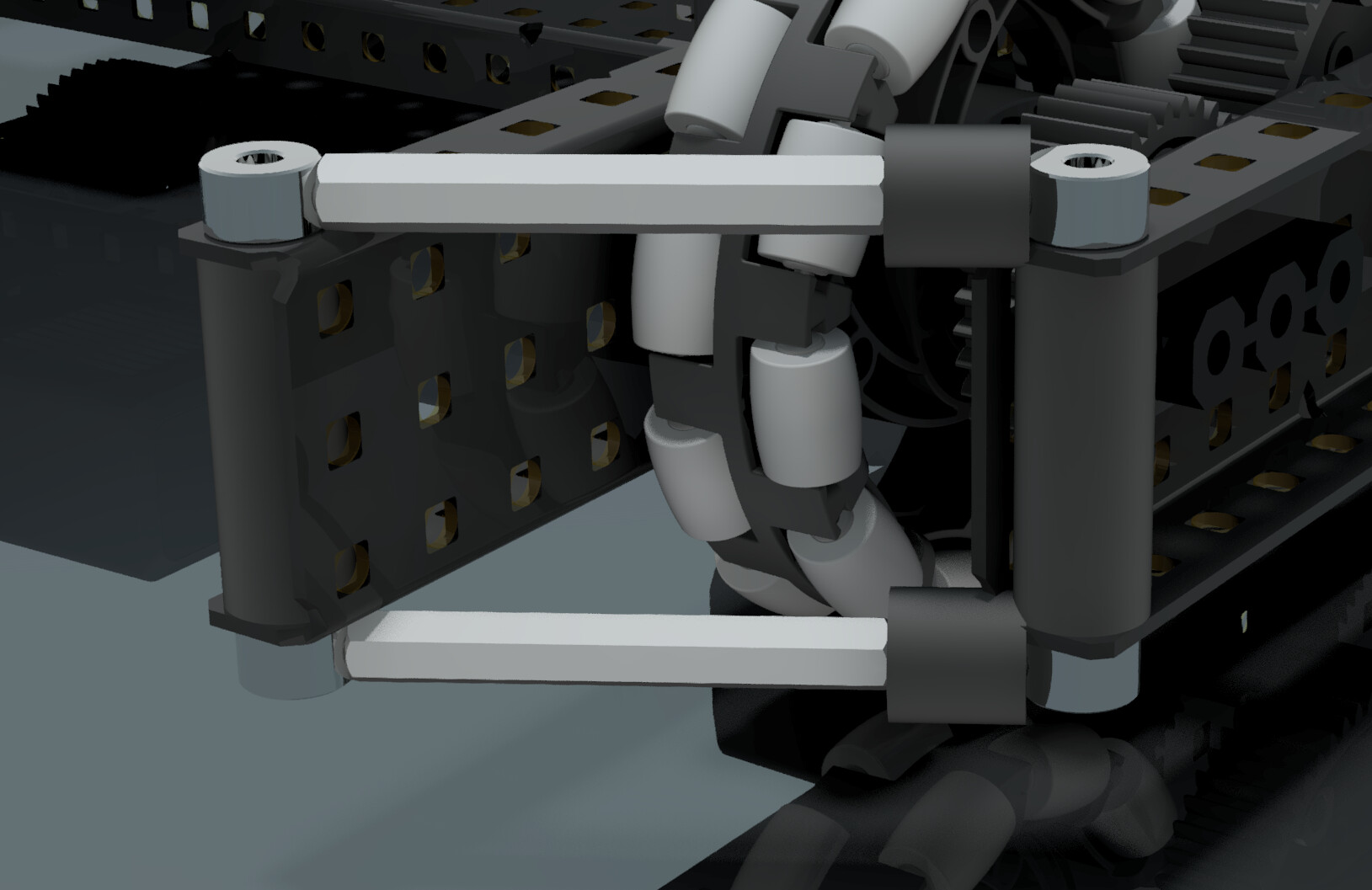
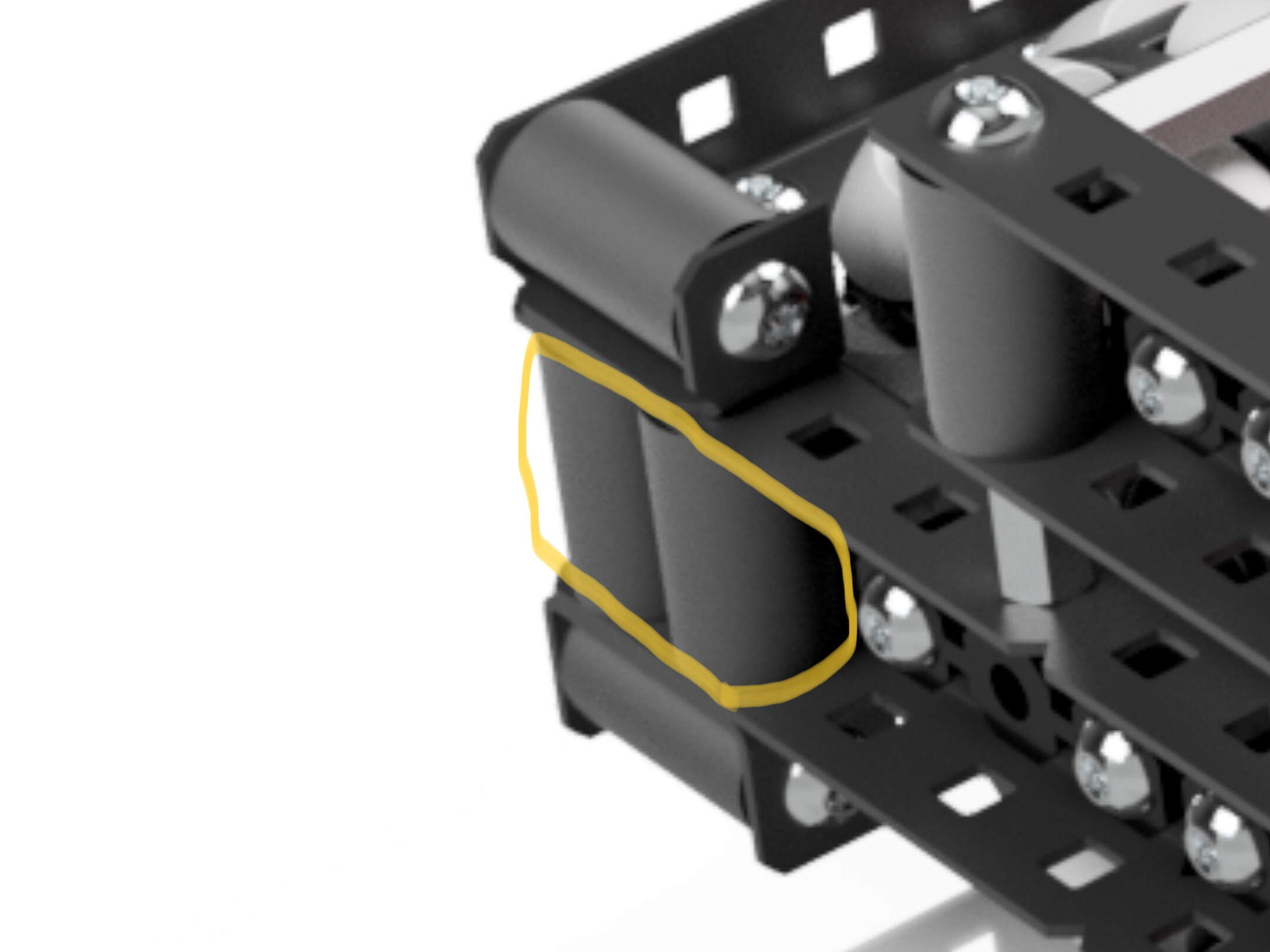
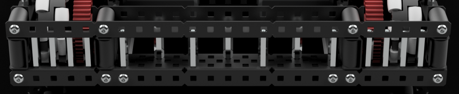
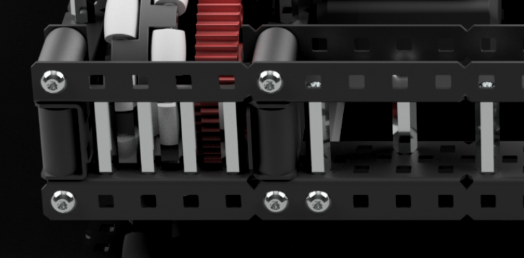
But on this version I opted for a more robust support, which uses a U channel with a notch cut in it for the wheel as well as standoffs to make a more rigid, robust, and compact brace.
This brace is more robust because it’s all one piece, and has multiple points of contact with each side of the drive. I also filled in the gap of the U channel with standoffs for even more strength. This is probably overkill, but it just ensures that this brace will be of the strongest build, and will be able to withstand any kind of defense or collisions your base may encounter, and it comes at a pretty low weight cost.
You may also notice the use of shaft collar standoff braces running along the top and bottom of the drive. These are not especially crucial to the drive, but they prevent the sides of the drive from being able to squish together or apart, and just add to the general rigidity of the drive.
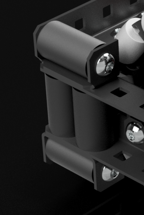
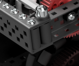
The next interesting brace I used on this drive was a modified C channel bumper in the back:
This is a similar style of bumper to what I used in my original quality drive:
But an issue with this kind of bumper is that your back wheels are not quite at the very back of your robot, which can be a problem if your robot tends to tip backwards.
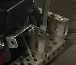
What I did to improve this was cut some notches in the c channels so that the wheel fit further back in the robot. I also filled in the gap between the c channels with standoffs to prevent them from bending inwards or outwards. (I did end up building the first quality drive, and I accidentally stepped on the rear bumper, and it did permanently bend down, but with standoffs there that wouldn’t have happened)
I also have a super simple cross brace doing down the middle of the drive. There’s nothing special about this, it simply connects one side of the drive to the other. It is important though, because it prevents the bumper of the drive from being able to twist, and one side of your drive to flex upwards or downwards from the other.
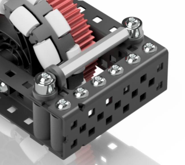
Motor Placement
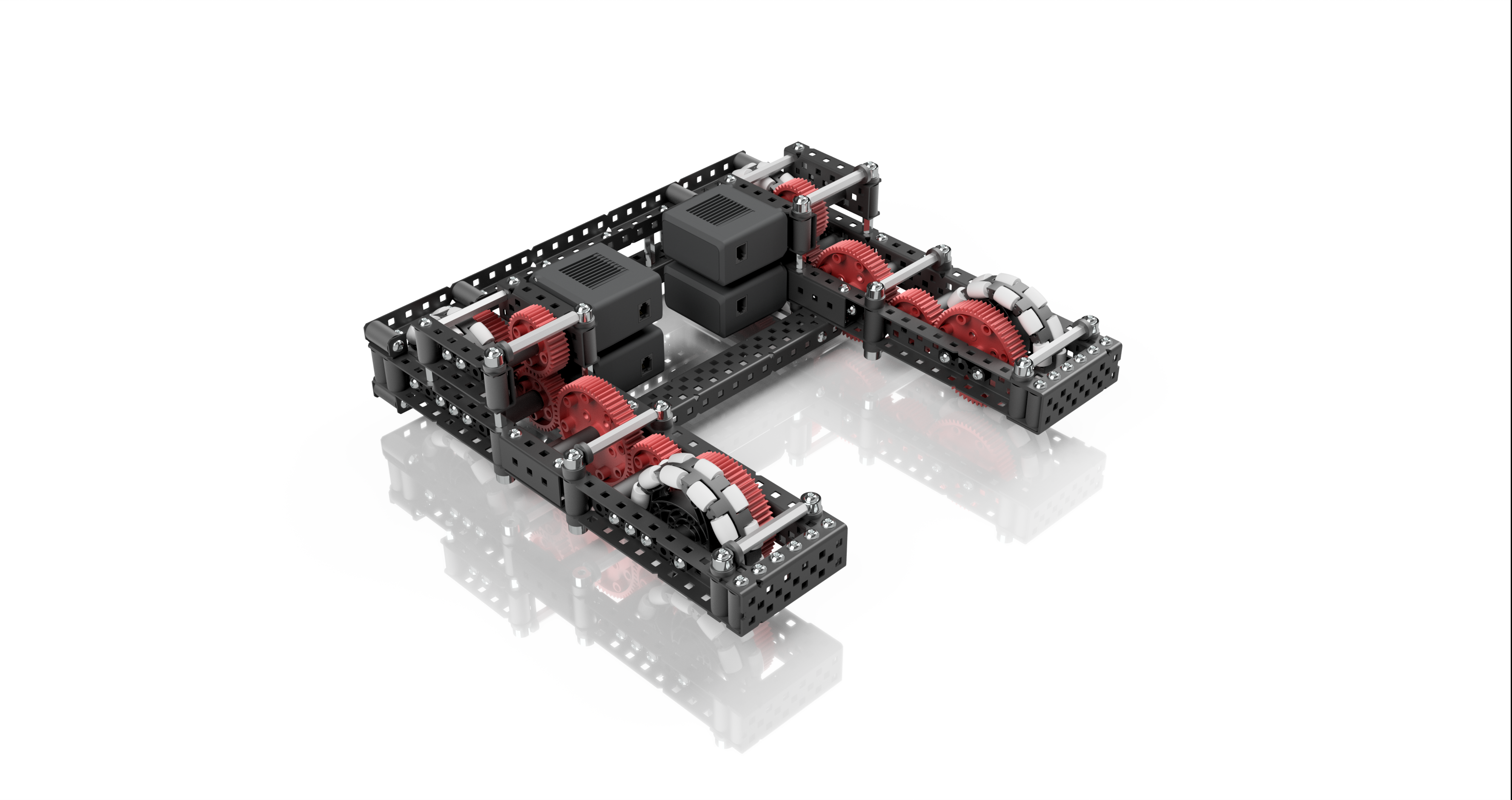
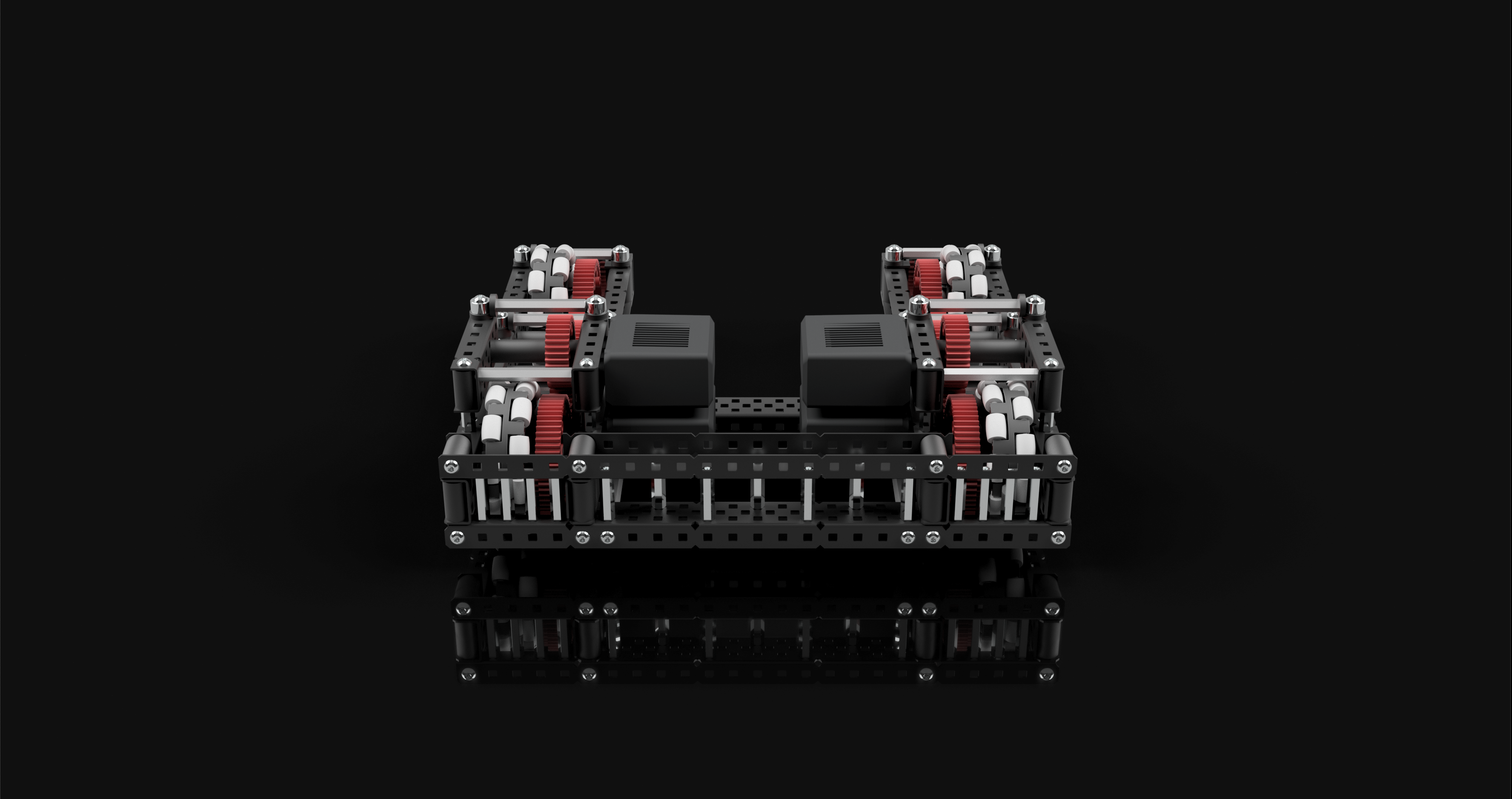
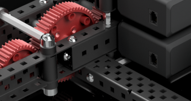
You may have noticed that I've stacked my motors in the back of the robot. I've chosen to do this as a way to preserve space at the front of the drive. This space could be useful in many ways, you could have intakes there, tracking wheels for odometry, any number of things really. And if you don't need anything to be there, the motors on this type of drive don't have to be stacked, I just did so as an example of a way to conserve space at the front of the drive.Renders
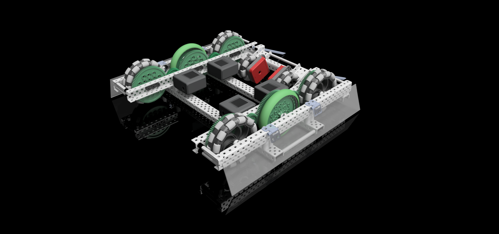
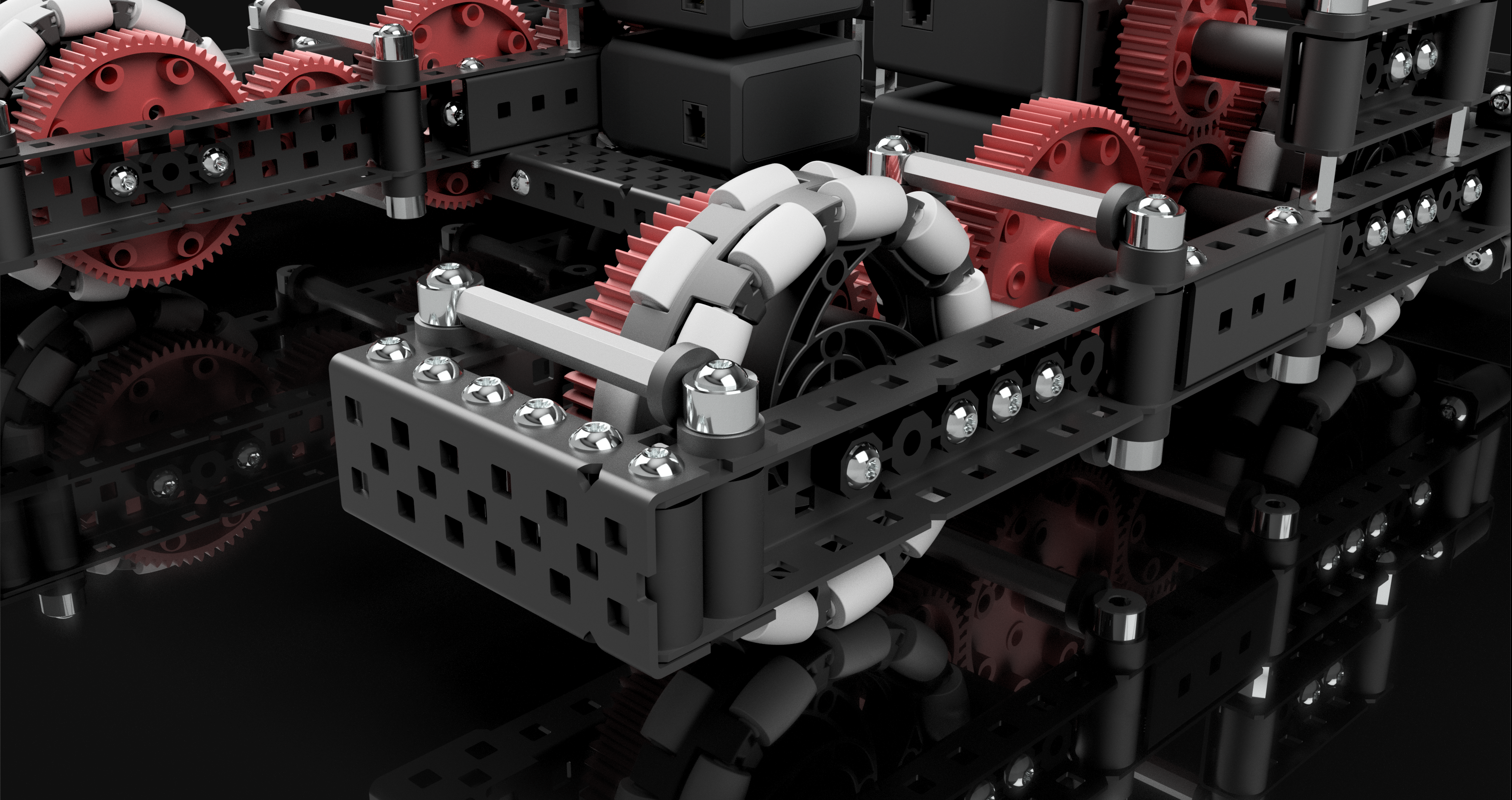
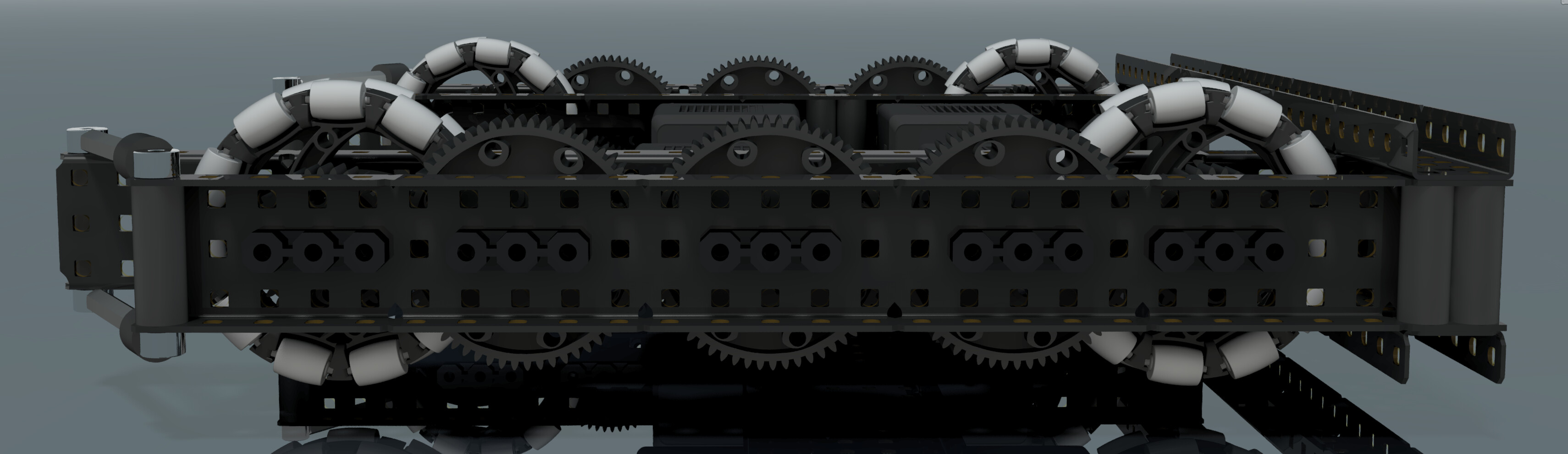
Here are all of the renders I made of this drive.
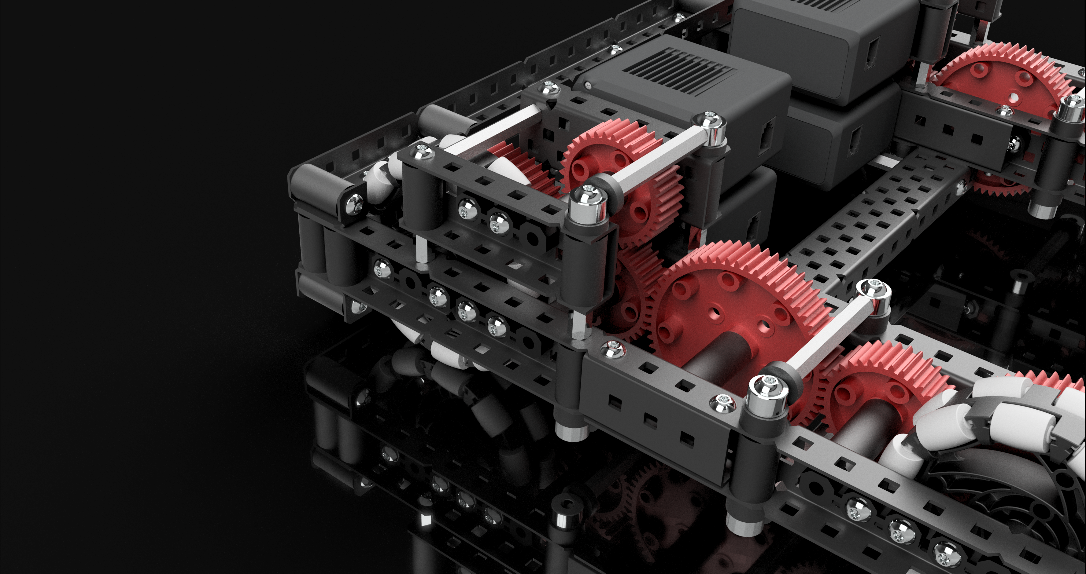
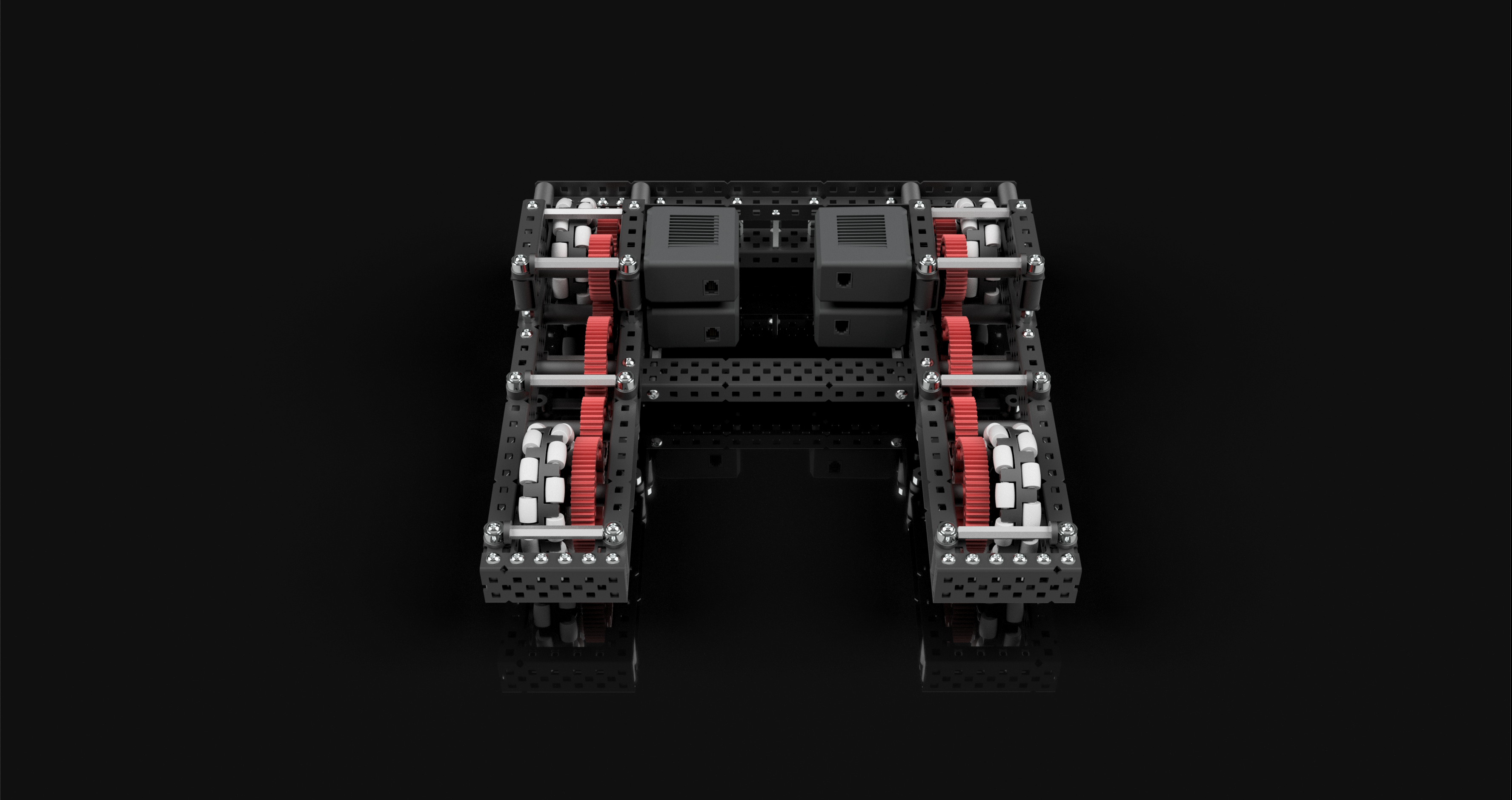
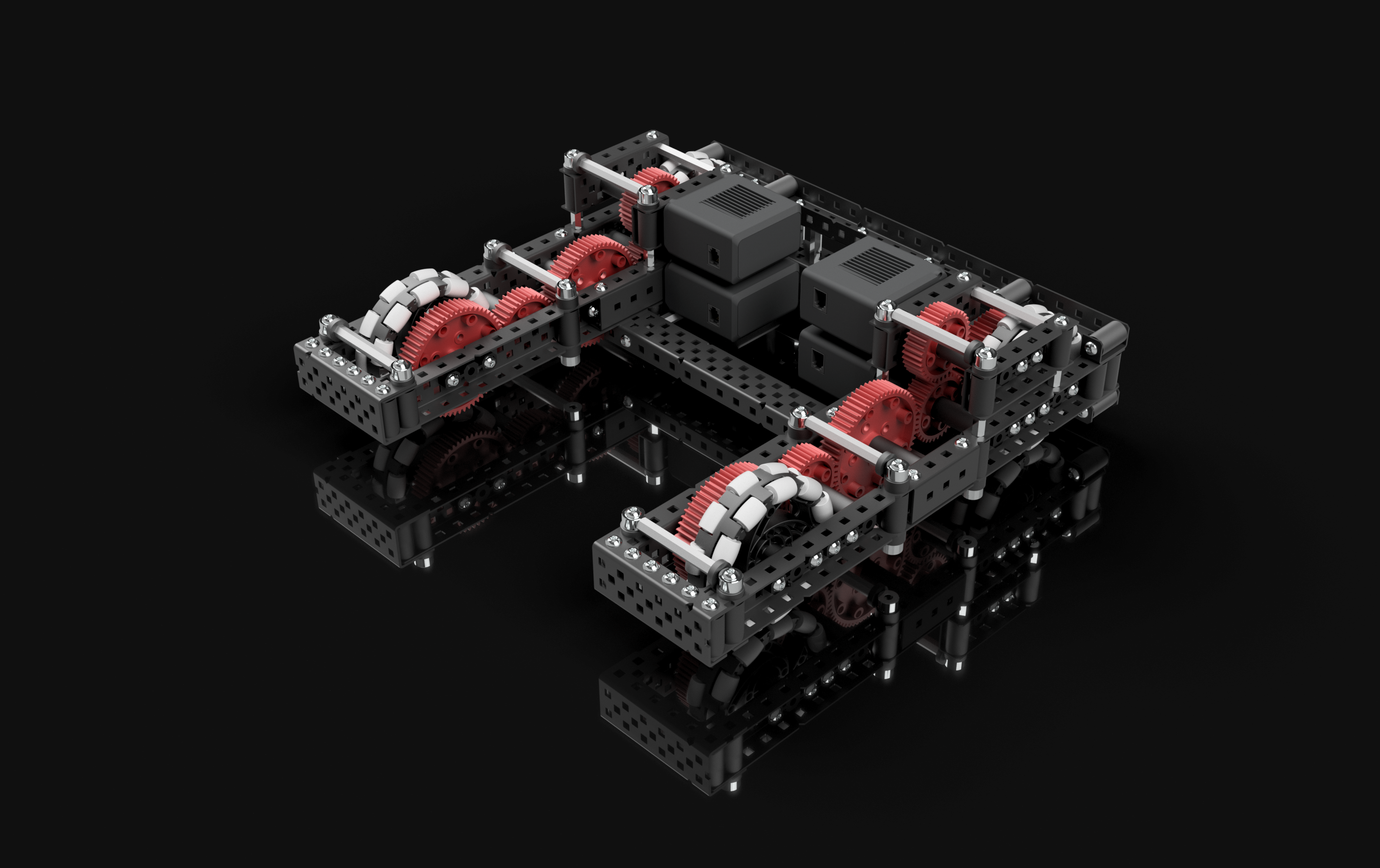
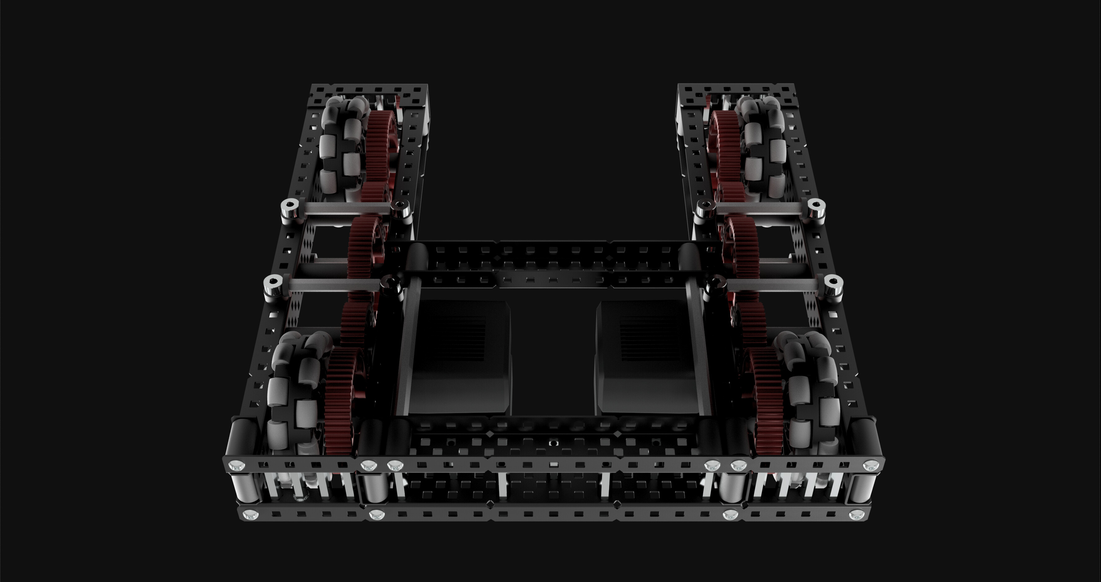
All of these renders were done by setting the background in inventor, tweaking the lighting, shadows, and reflection settings, and enabling raytracing on the highest quality.
CAD file
This time I’ve attached a zipped step file of the CAD file, with the request that you do not blindly holecount but instead study the drive model in order to learn from it. I think you can learn a lot from studying a CAD model of a robot.
QualityDrive2.zip (6.3 MB)
General Drive Designing
Here is some general information I think should be known when designing any sort of tank drive, not specific to this particular drive.
Design Choices
There are numerous design choices you have to make when designing a drive, I’ll list them here and provide options that I believe to be viable, and when you would want to use them.
Size
The size of your drive should not be an arbitrary thing, selected a random. It's important to consider what your entire robot is before selecting a suitable size. If you need to have something sticking out in front of your robot for example, making your drive shorter could be a good idea so you don't need to deploy that thing sticking out. Or maybe you don't need to have anything sticking out, and you're worried about your robot tipping, in which case having a really long drive might be a good idea so that you can't fall over. I really can't say when any size should or shouldn't be used, but if you take into consideration your entire robot, picking a size should be relatively straightforward.C Channel width
first off, you should be using C channels. anything else will suck for a drive.as far as your options go here, you have 2, 3 and 5 wide c channels to choose from. 2 wide is the most common, for good reason. It’s compact, light, and still pretty strong. If you don’t have a particular reason to use a larger size I would go for this. 3 wide c channel is pretty similar to 2 wide, except it’s slightly larger, slightly stronger (although just barely) and might give you some better mounting opportunities. I think using 3 wide c channel works well on a drive, but I wouldn’t use it unless you have a reason to. As far as 5 wide drives go, they definitely should not be used without a reason. They’re excellent for robots that want a heavy and very strong base, either for defense purposes or to have a lot center of gravity to avoid tipping. I would stay away from this unless you know what you’re doing, because they can be used effectively, but only with proper intent.
Wheel Size and Gear Ratio
Wheel size is a pretty basic decision, you have between 4", 3.25", and 2.75" wheels. there are other sizes, but not of omni wheels, and you really should be using omni wheels.All of these sizes are viable, but I prefer 3.25" wheels for reasons I describe earlier in this topic. Keep in mind that wheel size will effect your robot’s speed, as well as the height that your robot’s base is off the ground.
Gear ratio is a much more complicated decision, you first need to be aware of what kind of speed you’re after.
At the low end of the spectrum, for games that involve lots of small, short movements and heavy robots, like tower takeover, choosing a ratio around 200 rpm on 4" might be a good idea, for high torque and good acceleration.
At the top end, for a game like change up where robots weight very little, and need to zip around at high speeds, ratios from 300 to even 400 on 4" wheels might be more suitable.
It really depends on the game and your robot, make sure you can move fast enough that you aren’t going to be wasting time creeping around, but that you have enough torque to not stall under defense and intense matches.
In General
Just make sure you’ve thought out every aspect of your drive. It’s a great idea to use CAD so that you can plan it out in it’s entirety before even building. As a rule of thumb, every decision you make should have a valid reason, if it doesn’t you should be questioning if it’s the right decision to make.
Construction
The construction of your drive is the most important aspect, if you want your drive to perform well it has to be built well. I can’t discuss every nuance of build quality here, but I’ll go over the basics when it comes to drive construction.
Bracing
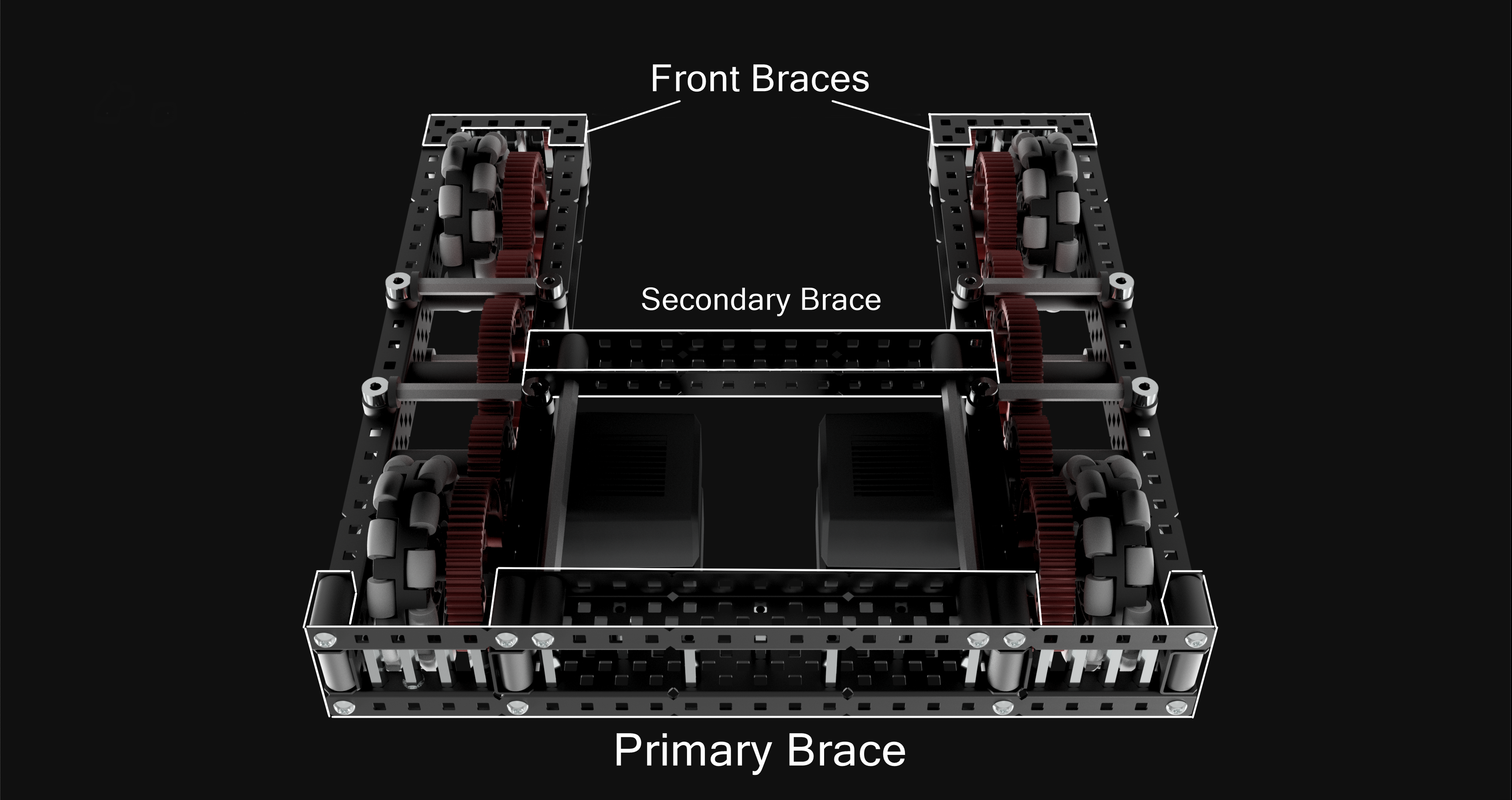
your drive needs to have proper bracing so that it stays rigid and cannot flex or deform. At a minimum you should have two cross braces between the two sides of your drive. The further apart these braces are, the more robust the drive will be. It's also a good idea to brace these braces, by which I mean reinforcing them so that they themselves cannot flex or bend.My preferred method of drive bracing is to create one primary brace, usually at the very back of the drive, and make it as strong as I can. This means multiple c channels, standoffs, box bolts, everything to keep this brace as rigid as possible.
Then I create a secondary brace, somewhere in the middle of the robot. This brace doesn’t have to be quite as strong as the primary brace, but it does need to be attached properly. That means box bolts to the c channel, and for added strength you could brace this brace to the primary brace, although this isn’t necessary. Because a drive usually has gears in the way, this brace can’t remain flush with the drive channels and span the entire width of the drive at the same time. I find that it’s better to connect the inner sides of the drive than it is to mount this brace away from the drive sides with standoffs and span the entire length.
it’s also important to have a brace at the front of each side of the drive, in order to keep the drive channels firmly connected. There are many ways to do this brace, you could simply use some short c channels, you could use standoff shaft collar taper bracing, or you could do something with U channels like I did in my drive.
I also find it’s helpful to have a few additional braces spanning each side of the drive. Since there are gears in the way, these braces will have to be elevated or lowered in order to fit. I used standoff shaft collar braces on my drive, since they have excellent tension/compression resistance and that’s their main purpose, to resist the drive channels from squishing together or flexing apart from each other in the middle.
Of course, this is just my preferred bracing method and it’s by no means the only one. There are infinitely many ways you could properly brace your drive, but just remember as a rule of thumb, your drive should not be able to flex a significant amount. A good test for drive rigidity is to grab the two sides of the drive at the front, and try pulling them apart, pushing them together, or rotating away from each other. If they can do any of these things a significant amount (there will always be some level of flex, especially with the rotating test) then you probably need more bracing. The goal here is for your drive to act as one completely rigid component.
Building Techniques
There are a few building techniques you should be using on your drive that will greatly increase the overall build quality.
Box Bolts
A box bolt is where you put a long screw through an entire c channel, and fill the gap with spacers or standoffs. This gives the connection vastly more strength, and you should be doing this wherever possible.
in situations where you want to have a box bolt, but something else is in the way, for example a bearing, using C channel couplers instead is an alternative.
Standoff Reinforcing
Standoffs as a part are incredibly strong, especially in shorter lengths. I like to use them to fill in a gap between 2 peices of metal, which greatly increases the strength of the metal you’re reinforcing.
Often times this is unnecessary, and you might want to avoid over-using this technique, especially if weight is a concern. However standoffs when used like this do add a lot of extra strength for relatively little extra weight.
Axle Friction Reduction
Bearings need to be used on your drive. This is just the most basic of construction rules. But there are some more specific ways you can reduce friction on your axles as much as possible.
First off, you don’t need to have bearings on the motor side of a driven axle. Your motor can act as the other bearing. If you have a particularly heavy robot, or your worried about the additional stress on the motor, you can certainly put a bearing there and it’s not going to be terrible, but it will add some more friction and isn’t necessary.
Secondly, when ever you have a shaft going through some metal, you can use a drill to slightly widen the hole that the shaft is going through. This prevents the shaft from ever clipping the edges of the hole if your bearing is subtly misaligned or worn down, and is a great way to prevent large amounts of friction.
And lastly, wherever a motor isn’t connected to a shaft, you can use a screw joint instead. I didn’t actually do this for the drive I designed because it isn’t the most important thing, but it can help to reduce friction. Basically just bolt a screw into your drive channels, and attach your gears and wheels onto the screw with free-spinning inserts so that instead of an axle rotating in a bearing, you have your gears and wheels spinning on a screw.
here is a video on different types of joints, this video is made more for metal rotating with other metal, not gears or wheels, but the concept is the same, just replace the rotating metal and bearing with a gear or wheel with free spinning inserts.
Drive Troubleshooting
Drives are the most important part of a robot, which means it’s crucial that they function as intended. But drives can also be one of the trickiest parts of the robot, because there is a lot that can go wrong with them. I’ll go over some common drive problems and what the cause/solution might be.
Drive Stalling
This is a very common issue, where after a few minutes or maybe even less of driving, the motors get too hot and they begin to stall, rendering your entire robot practically non-functional. The most common culprit of this issue is simply friction. If you have a lot of friction in your drive, the motor have to work much harder to overcome it, and will overheat more rapidly.friction can be caused by any number of things, but usually it’s due to misaligned bearings rubbing against axles. Make sure that bearings are lined up perfectly, and that they’re fully seated in the holes they’re mounted to. Sometimes your entire drive channels might be misaligned, because of the slop that screws have in the larger vex holes. ensure that all your connections are truly square, that is everything you want to be a 90 degree angle actually is a 90 degree angle.
friction could also be caused by having overly packed spacers, overly tight shaft collars, or in the case of screw joints overly tightened nylocks.
Also check that none of your gears or wheels are rubbing against anything.
Drive stalling can also be simply due to an overly aggressive gear ratio. A 360 rpm drive is not going to be able to work with a 25 lb robot. You need to make sure you pick a ratio according to the weight of your robot otherwise it won’t have enough torque.
Drive Leaning
Another common issue is that your drive might drift to one side or the other when you want it to be moving in a straight line. This is usually caused by one side of your drive having more friction than the other, which means it will accelerate slower than the other side, and have a slightly slower top speed than the other side, resulting in your robot moving in a giant arc instead of a straight line. To fix this you need to reduce friction on the side that’s moving slower.
Testing for Drive Friction
A good way to test your drive for friction is to disengage your shafts from the motors, and try to free-spin your wheels. They should be able to spin freely for at least a few seconds, depending on how many gears you have.
A good way to test for a friction imbalance between the two sides is to place your robot so that none of the wheels are touching the ground, and then drive forward at full throttle. Then suddenly stop driving the motors, and watch to see if one side of your drive comes to a stop before the other. if it does, that means it has more friction.
How to Design a Drive
The most important thing when creating a drive is to plan it before you build it. Because if you don’t, you’ll find yourself running into unforeseen problems, and you’ll either have to cut corners or redo your drive to fix them, which leads to an overall lack of focus and intent in your drive’s function as well as general jankiness.
The first thing you should do is decide what your drive needs to do. obviously it needs to move around, but what does it need to do in order to function with the rest of your robot? maybe it needs to have a space open in the front for an intake, maybe it needs to be small, maybe it needs to be narrow and long, you have to decide these things first, which means you need to design your entire robot before your drive.
No decision you make should be arbitrary, everything needs to have a reason.
The very best advice I can give for people wanting to design a quality drive, or a quality robot in general, is to use CAD software to do so. I say it all the time, but it’s true. CAD is one of the most powerful planning tools you can use, you can essentially create instructions for your entire robot without touching a single part. This means you can solve technical oversights in seconds, instead of undoing hours of progress or finding janky solutions while building on a whim. You can know exactly what will or won’t fit, and you can experiment with different construction techniques without having to assemble or cut any parts. And most importantly, every time you CAD something your ability to design and build robots improves. Its the best way to rapidly grow your skill as a designer and a builder, and everyone should be doing it. Please, for your own sake, use CAD.
Hopefully this topic will be helpful to people looking to construct a drive of quality build. If anyone has anything to add or any other drive related resources, please do share them below.
This robot and all the renders were done in Autodesk Inventor.