Due to frequent questions and discussions on drive speeds, but not a lot of resources on the layouts of the possible gearings themselves, I’ve created this resource for people to see a catalogue of drive speeds that I’ve deemed as viable, and some commentary on each layout.
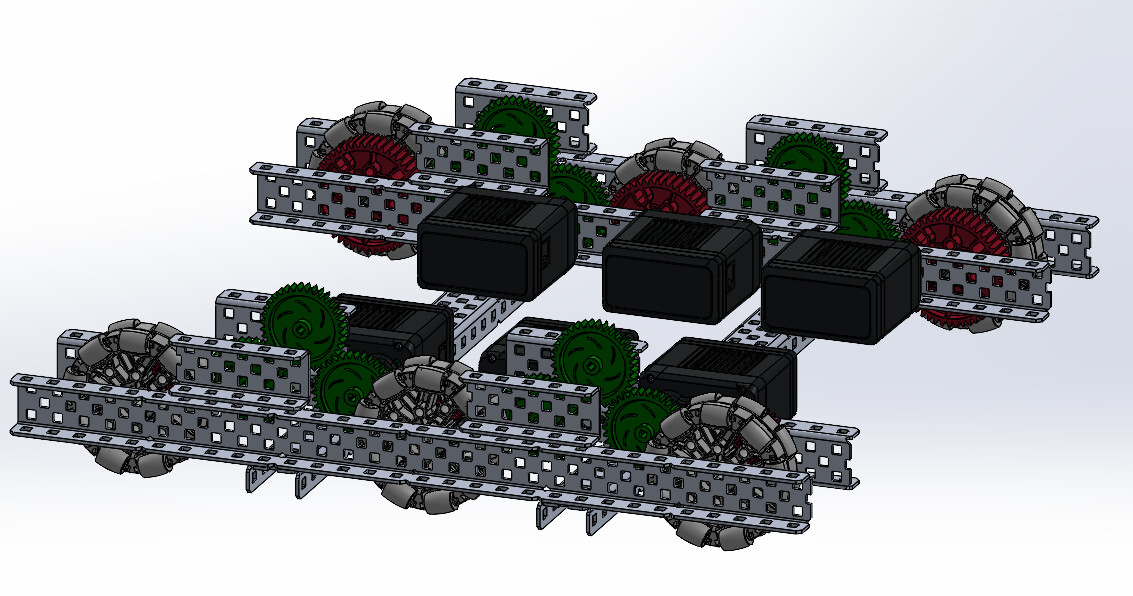
All drives shown here are on 6 motors, and all drives here are compatible with center traction wheel. (some drives have 8 wheels so traction will be offset from center). The layouts shown can easily be translated to 4 motor layouts, although it is worth noting that not all of these ratios will have enough torque with only 4 motors.
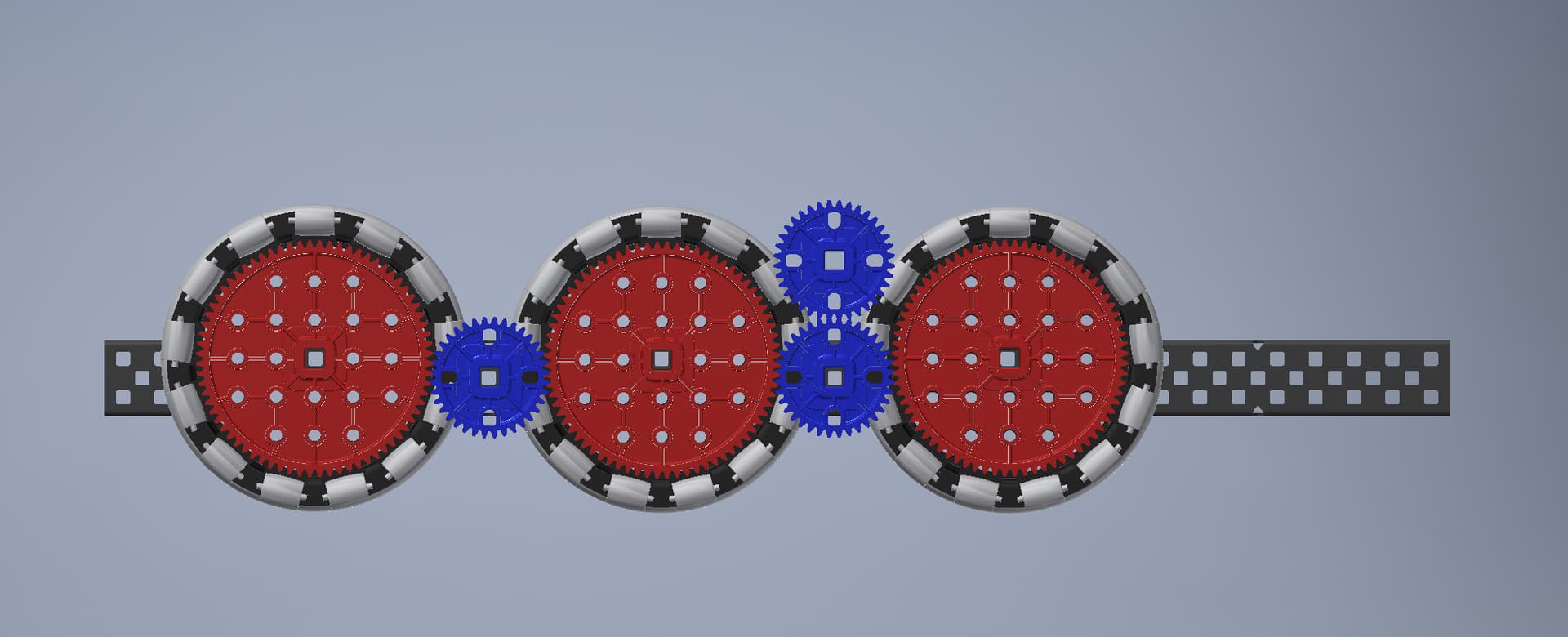
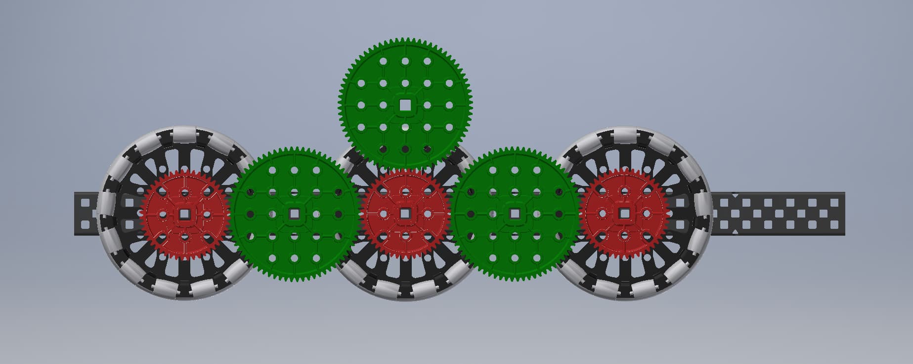
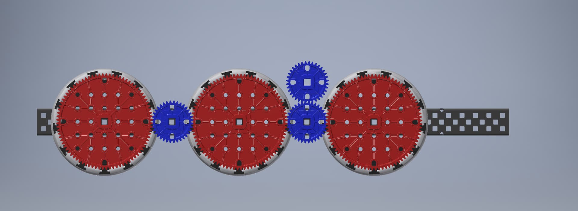
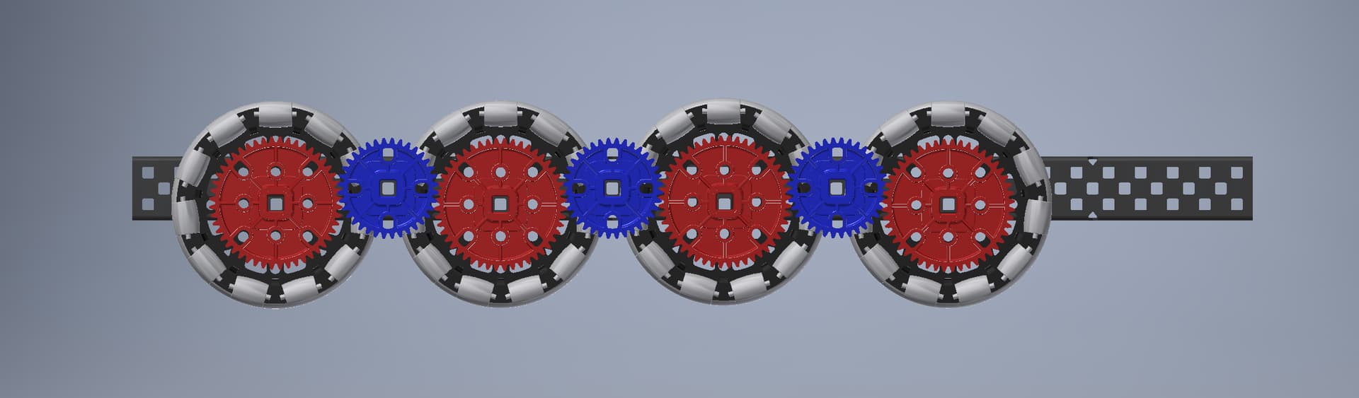
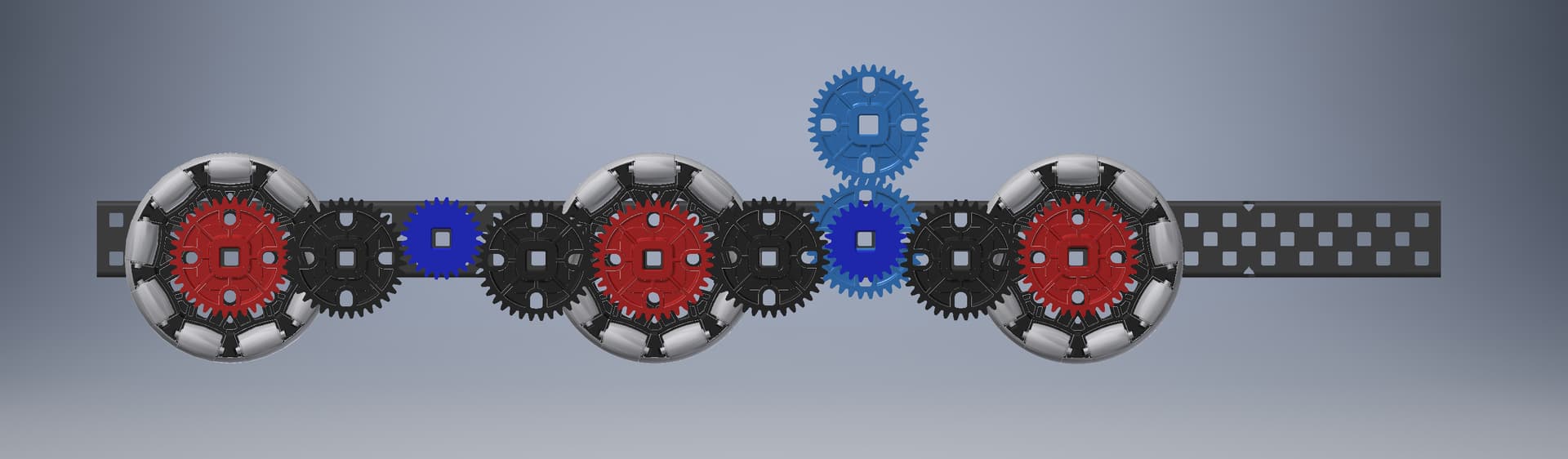
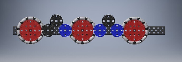
For context, red gears are the driving gears in the setup, blue gears and ones driven on 600 rpm motors, green gears are ones driven on 200 rpm motors, and black gears are idlers.
4" wheels
300 rpm (62.8 in/sec)
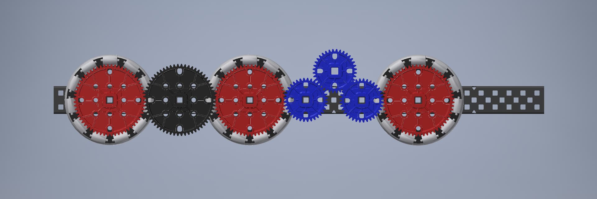
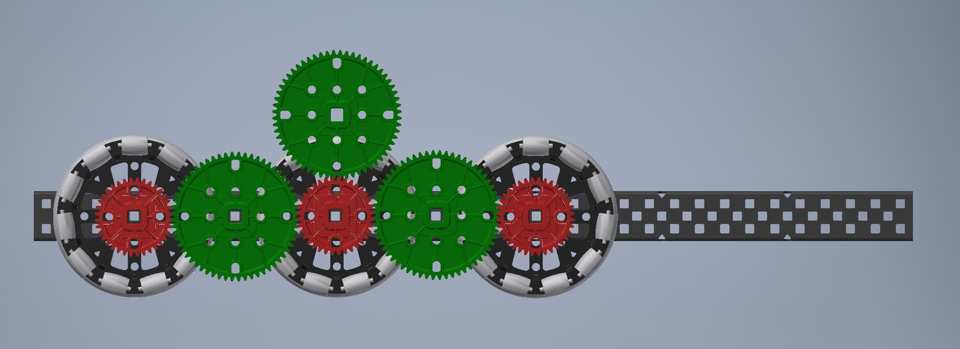
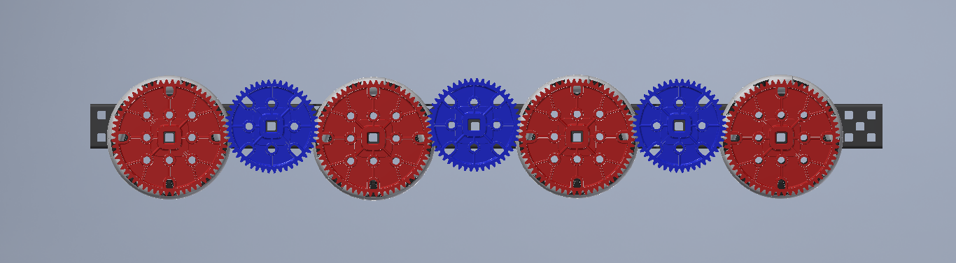
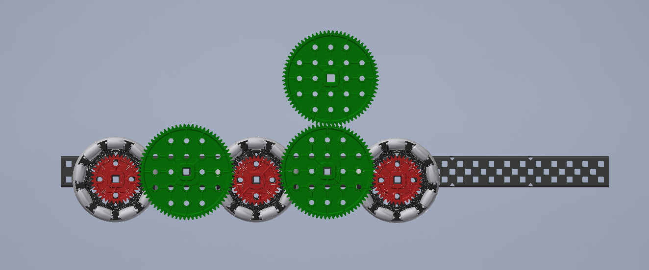
600 rpm geared down 36:72
this is a super nice layout, probably the best on 4" wheels.
I kind of hate how bulky this ratio is. Even though it only uses 6 gears and has no idlers, the raised gear means you have to mount a motor so high up. A better alternative could be to remove middle wheel and then bring down the raised 84t gear, reducing gear count to only 5, sacrificing the ability to do center traction.
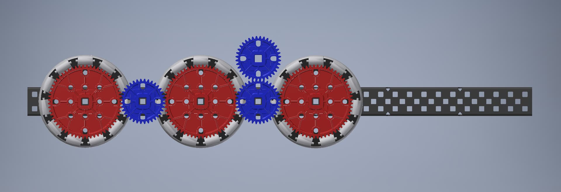
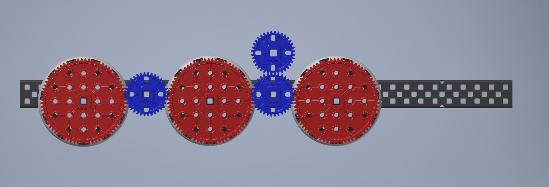
600 rpm geared down 36:48
very fast, needs to be built very well and driven very skillfully to be viable. Using an 8 wheeled layout like this gives it a reasonable length, though you could remove one wheel and stack the last motor if you’re ok with a very short drive.
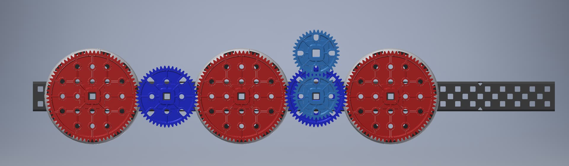
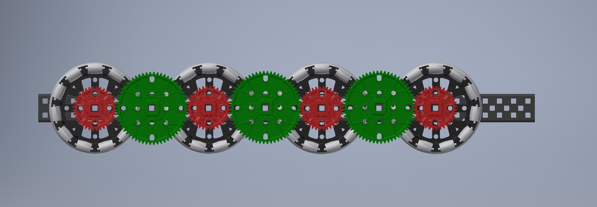
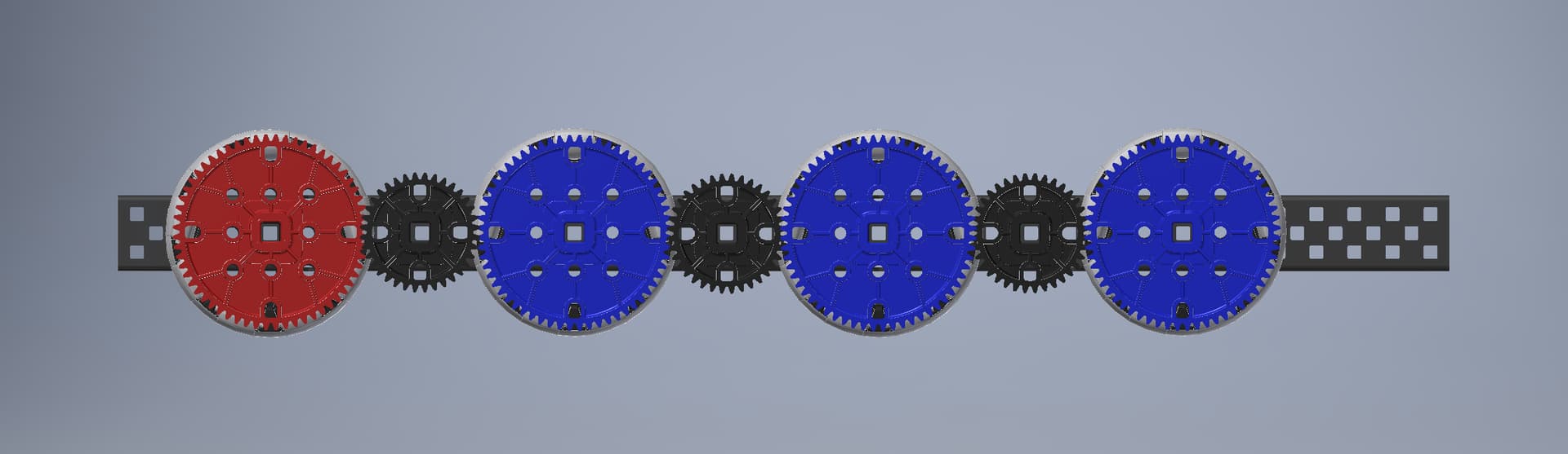
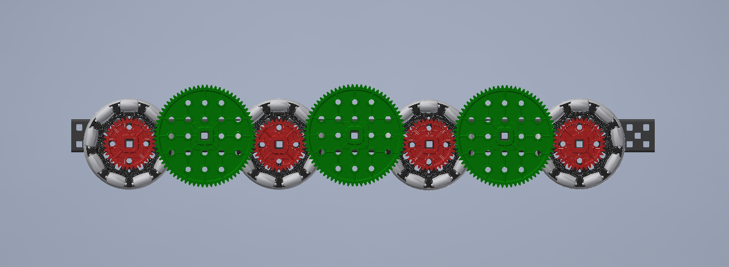
600 rpm geared down 48:72
In my opinion this is the single best drive layout. It has the minimum possible number of gears, is a great length, and lets you compact the stacked motor very low using a 36:36 compound gearing. It’s pretty fast though so you do need some driver ability to control it well.
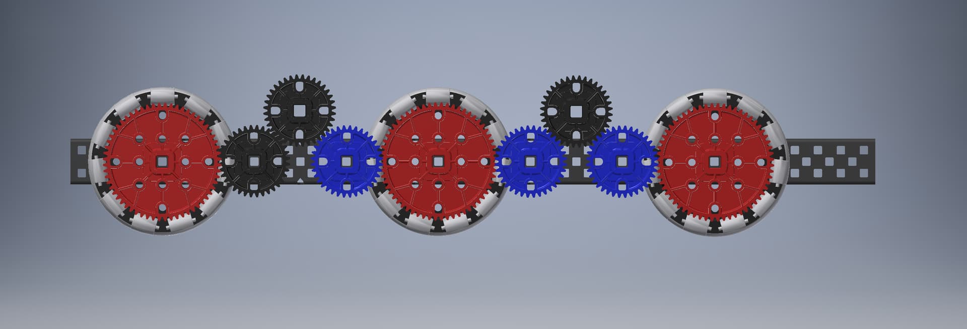
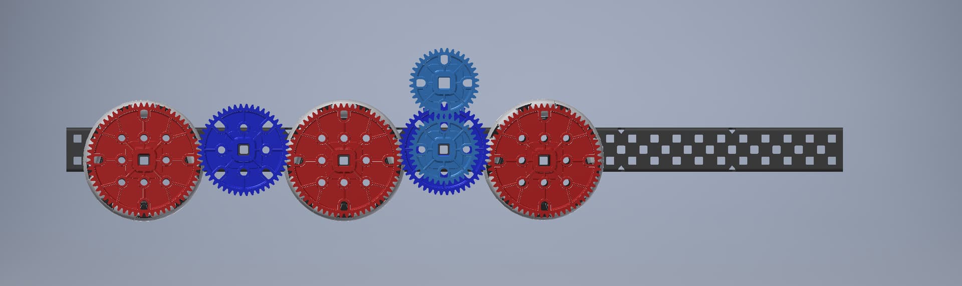
Works for longer robots, and has a still reasonable gear count, except that in order to get 3 motors to drive 3 36t gears like this, you need to mount the raised motor at an unusual angle. I do not recommend.
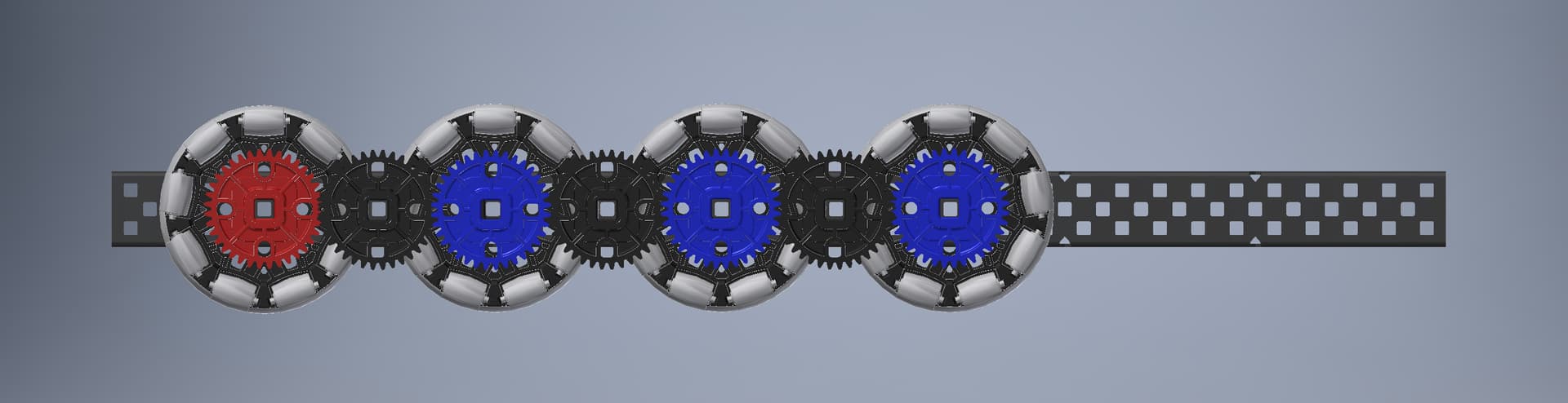
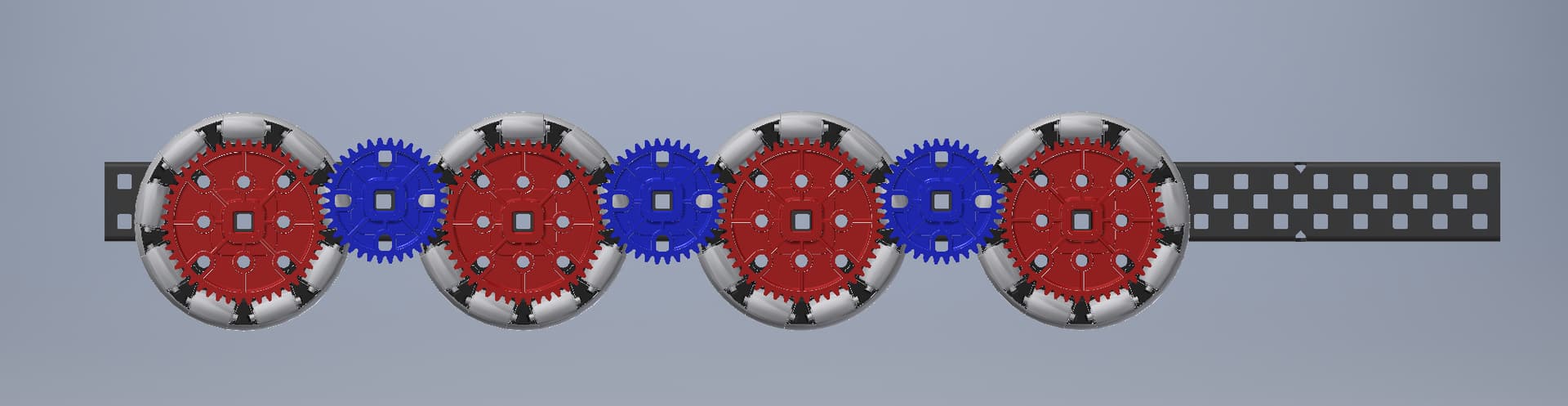
Really nice layout, but it is pretty slow. Slowest speed I would recommend to a team looking to gear their drive. Use this if you want a lot of torque and don’t care about moving all that fast.
both of these are decent, though one is long and one short. It is also pretty acceptable to just direct drive 6 wheels without gearing them together, but only with 600 rpm drives, so if you really want to go this fast than it might be preferrable just to not have any gearing at all. There are significant drawbacks to doing this though, and in general I don’t recommend going this fast unless you know exactly what you’re doing, in which case you probably don’t need to be reading this.
Overall, I would say that speeds lower than 62 in/sec will work well even for 4m drives, but ones faster than this will probably have issues. I also wouldn’t go beyond 70 in/sec unless you really know what you’re doing.
This catalogue is obviously only showing a limited selection of layouts, and the amount of variety you can get, especially if you remove middle wheels or use 4 motors, is virtually limitless. But the ones I’ve shown here are enough to cover the full range of use cases, and I hope this resource is helpful to people looking to explore their drive gearing options.
If you have anything to add to this resource, or questions you want to ask, please do so.
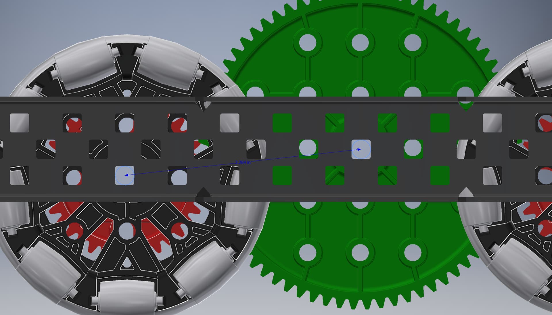
for example, a 36t gear and a 72t gear will mesh with each other at 2.25" center distance. But because inline holes only occur at 0.5" intervals, this isn’t possible to do inline without drilling new holes or something. But if you offset one of the gears up or down to one of the other rows, the gap becomes almost perfect. in this case, the gap is 2.264", which is still close enough for the teeth to mesh well, but doesn’t cause any excess friction. Gearing this way is pretty common practice when combining the new and old gear sizes, and I’ve seen teams have success with it on many different drive layouts.
it is worth noting that this distance between offset holes becomes close and closer to the ideal 0.25" increments the further apart the holes are on the channel, but the gap is always slightly greater, never less. So if you try to connect two gears like this that are small enough (12t and 24t for example), you might have an issue where the mesh is too loose. But for most gear sizes you’d use on a drive, it’s close enough to work.
Right, I see that – but when meshing the not at all new 36t to 60t or 72t, you don’t have to offset (as seen in your 360 and 333 rpm models.) I see teams using the offset anyway. Is it preferable to have a lighter gear mesh for reduced friction?
Edit: none of that is correct - product of a brain fart.
I have not seen teams do this, and I don’t think it’s possible to achieve a good mesh between 12, 36, 60, or 84 tooth gears, or between 24, 48, and 72t if you offset them in this way.
Sometimes you can offset the gears by a lot, raising them up on a completely different channel, not just by using a different hole in the c channel, and that can be used to mount motors in better places, or make gearing more compact length-wise.
I’ve heard that using 60t gears with 2.75" omnis doesn’t work great as the gear diameter is too close to that of the wheel. Have you tested this?
Also, for some ratios, such as 36 to 36 on 2.75 omnis and 36:48 on 3.25, the shaft is super close to the wheel and you will have to use .25" spacers on the shaft and a shaft collar by the motor, screwjoint it with a nylock at the end to hold the gear down, or something else.
Nice resource though.
60t gears work fine on 2.75” wheels when they are on the same shaft on the wheel. It’s a little sketchy when not on the wheel shafts, but on a light robot it works.
And yes, the shaft clearance is very tight in some of the layouts. But very doable.
you said that having the stacked offset gears for 360rpm on 3.25 is awful. i was considering doing something like that for 450rpm on 2.75in rpm is there something inherently wrong with it or is it just because there are better option other for more compact?
I just don’t like how many gears there are. 9 gears is kind of a lot when you have similar speed options that use a lot fewer, like 400 rpm 3.25", 300 rpm 4", or 450 rpm 2.75". All three of these layouts have pretty comparable speeds, but only use 6-7 gears.
of course, gearing 360 this way is actually really common, and totally works. I’m just not a fan of having more joints than necessary, and there are plenty of options out there that don’t use so many gears.
You mentioned that traction wheels could be offset from the center. Our team is considering this, do you know if there are any disadvantages of having an offset traction wheel compared to just a normal centered one?
Apologies for reviving an old topic, but I have question about this specific drivetrain (360 3.25”)
I was wondering if it would be possible to put a 12 tooth gear in between the 36 tooth gears rather than the offset 36 tooth gears. If it is possible, is there anything inherently wrong with doing this? The only problem that comes to my mind is increased friction due to the higher speed of the 12 tooth gear. Thank you for any responses.
Yeah, so generally in VEX, the faster something spins, the more friction it will have. Small imperfections in the shaft/bearings will be much more pronounced at higher speeds.
In this case, the 12t gear will be sandwiched between two 36t gears. Because of this 600 rpm 3:1 ratio, the 12t gear will be spinning at 1800 rpm.
This will inherently cause more friction than running the above drive setup, since the 36t raised gears (idlers) are spinning at a much more reasonable 600 rpm.
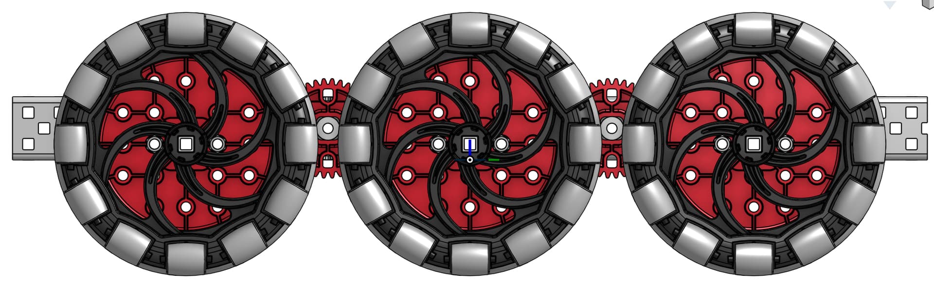
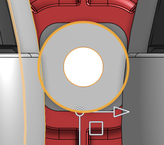
So sorry for reviving this topic yet again but I was making a CAD model of the 300RPM on 4" Omni-wheels also feature in this post and came across an issue when attempting to add spacers to the 36t gears.
As seen above, when a 3/8" OD spacer is put on the same axle as the 36t gear, the spacers clips into the rollers on the adjacent omni-wheels. Has anyone else encountered this problem or have any ideas on how to remedy this?
Sorry again for reviving this thread.